~ Click Photos to Enlarge ~
Rolly's
EX
all content Copyright 2010 - permission is
required for republication
|
~ Click Photos to Enlarge ~ |
||
|
|
|
|
|
|
|
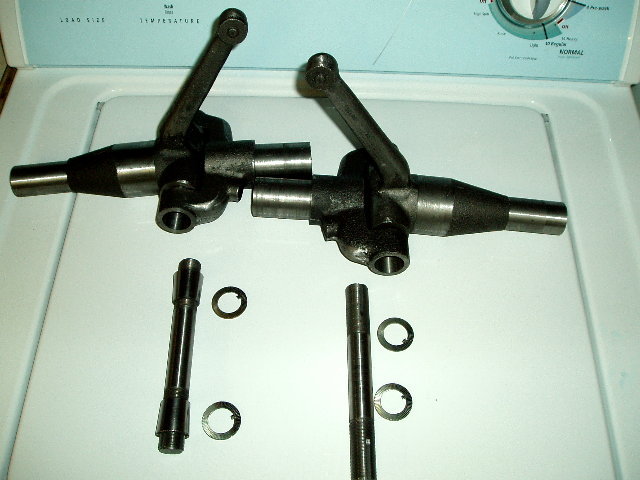
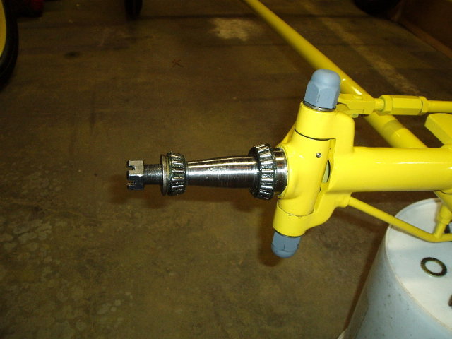
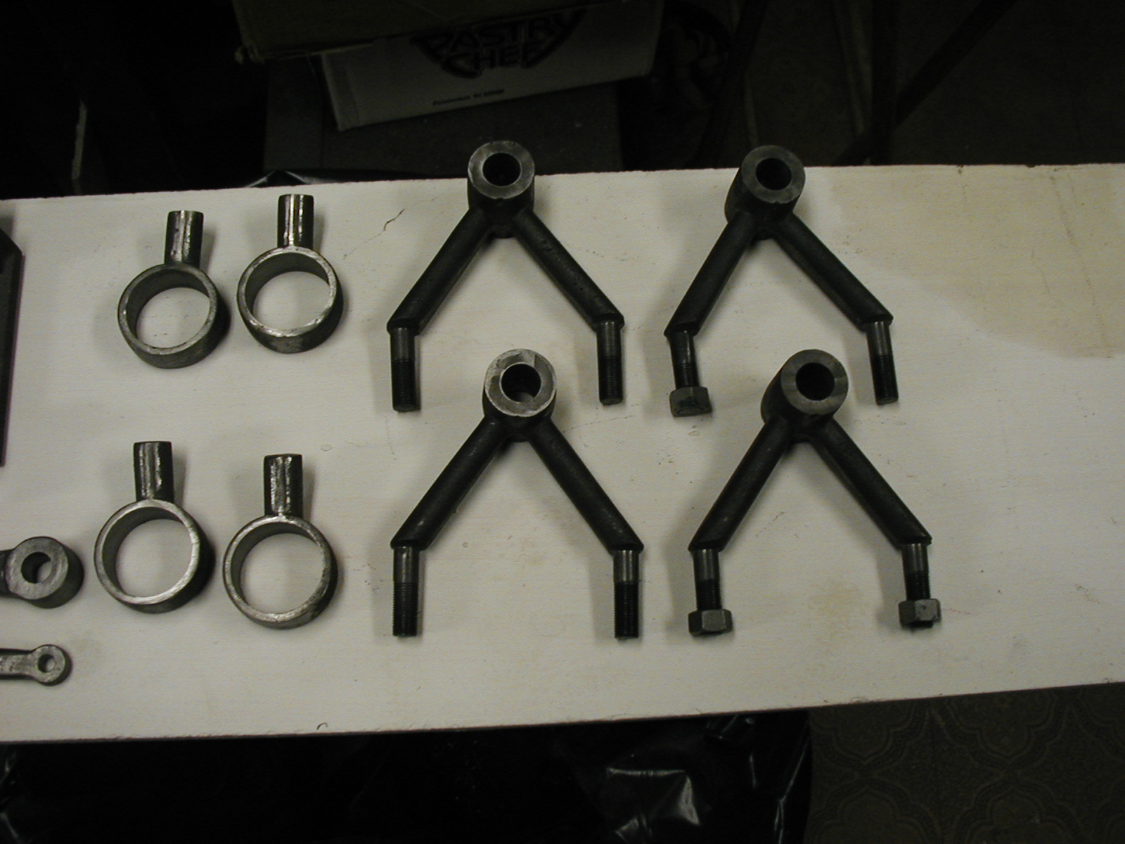
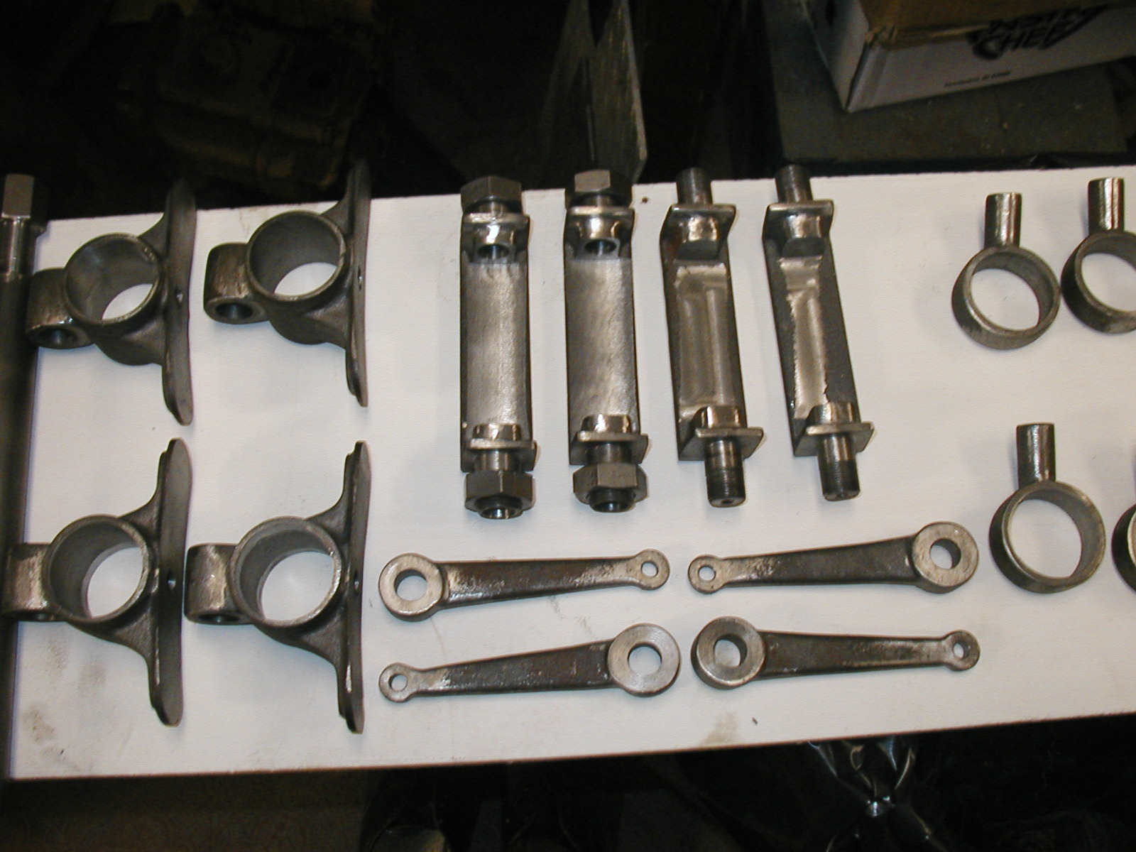
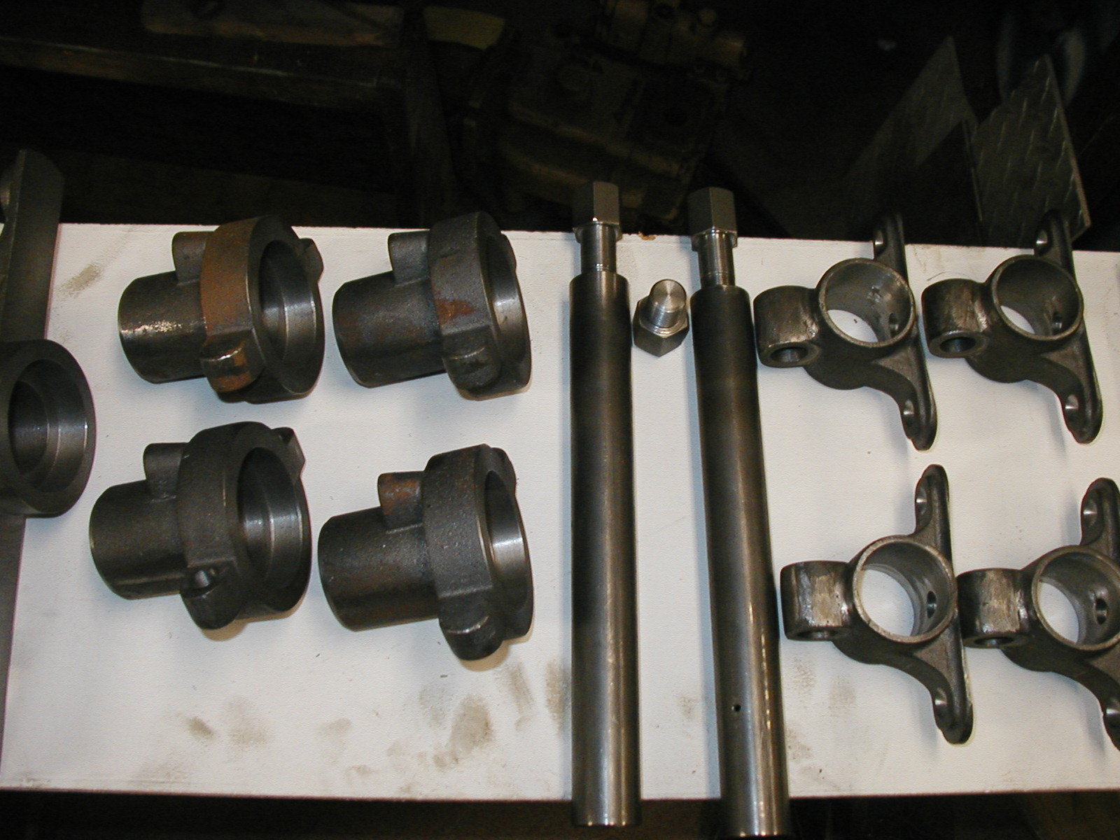
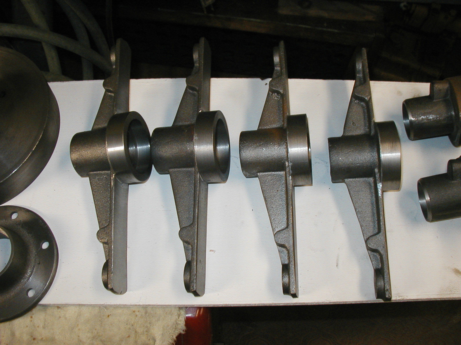
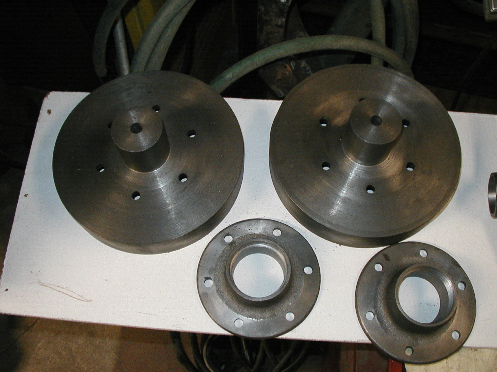
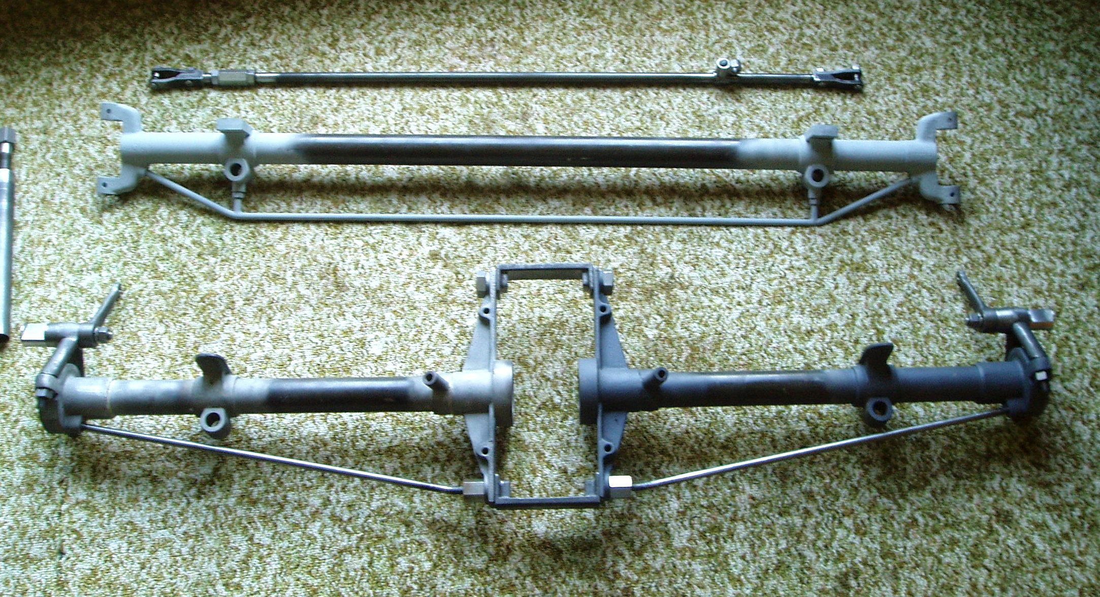
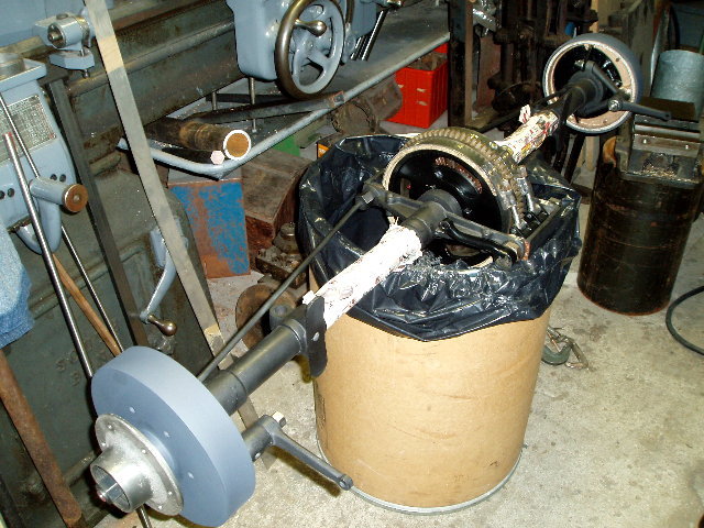
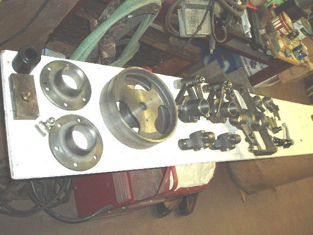
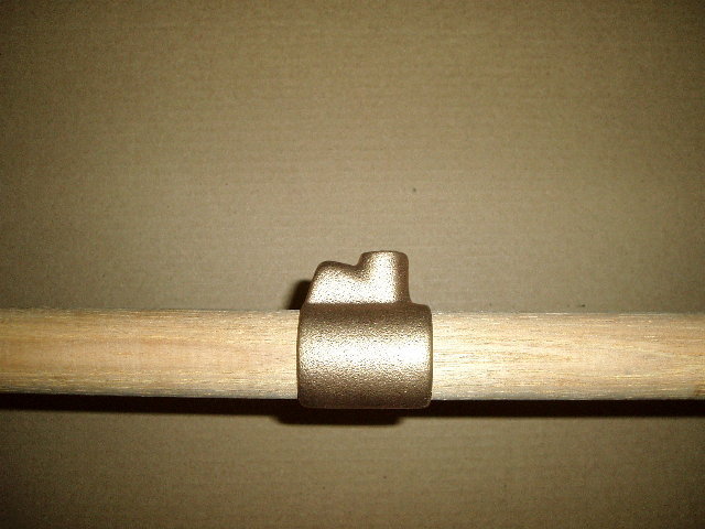
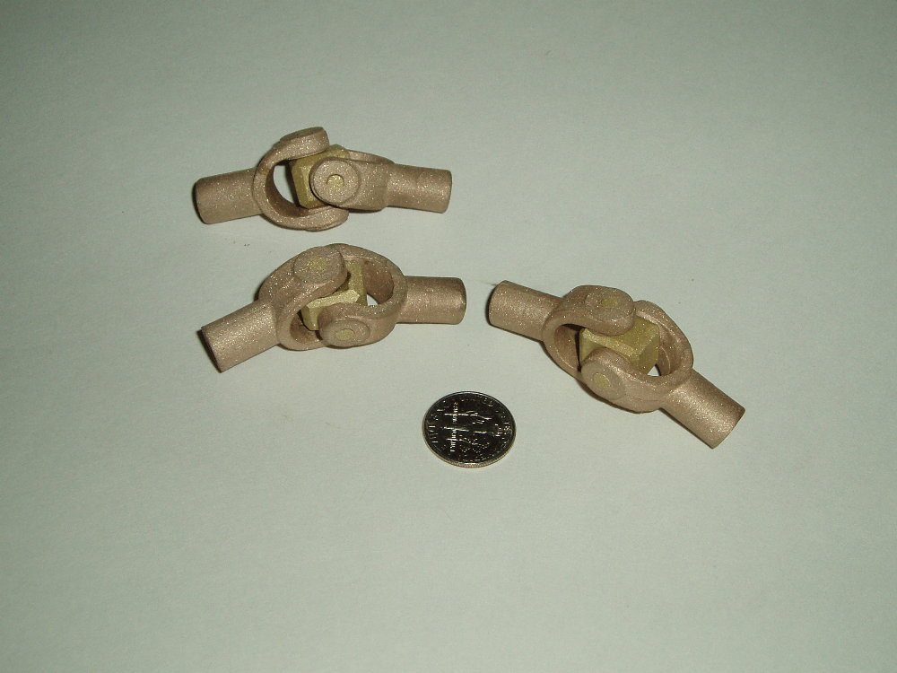
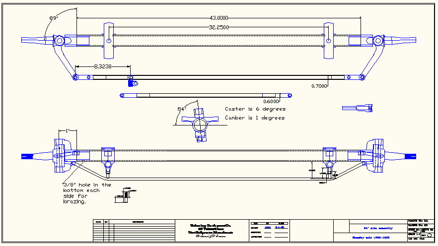
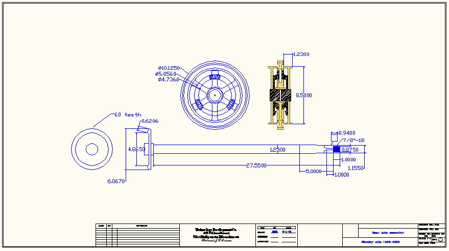
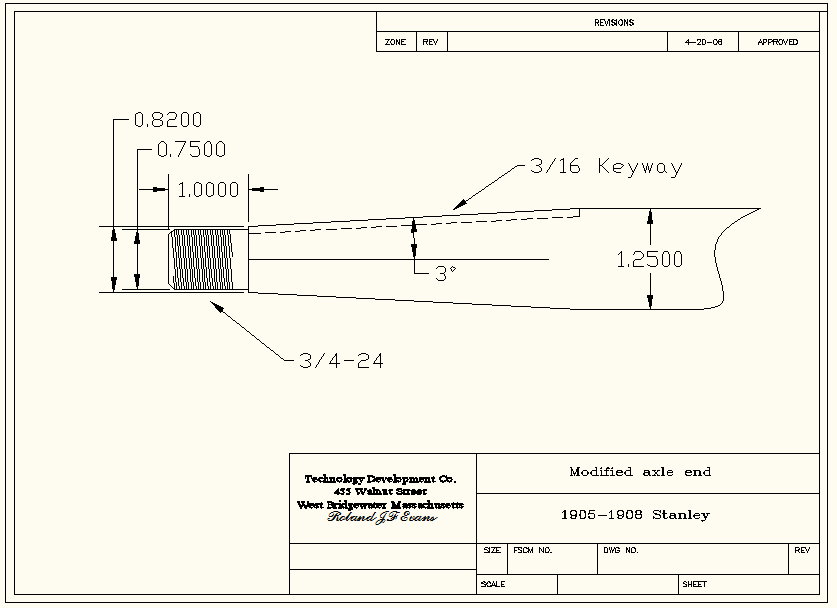
EX Front Axle |
|||||||||||||
|
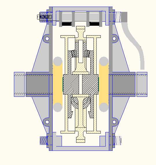
CAD Drawings in JPEG |
Click Photos to Enlarge |
||||||||||||
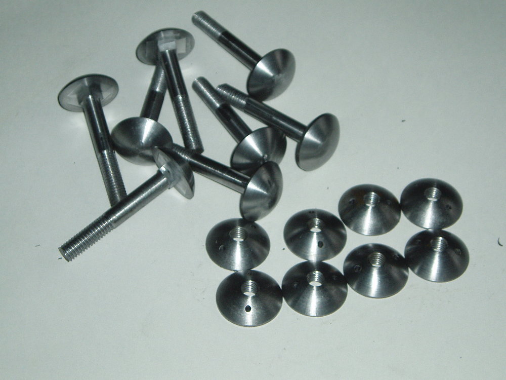
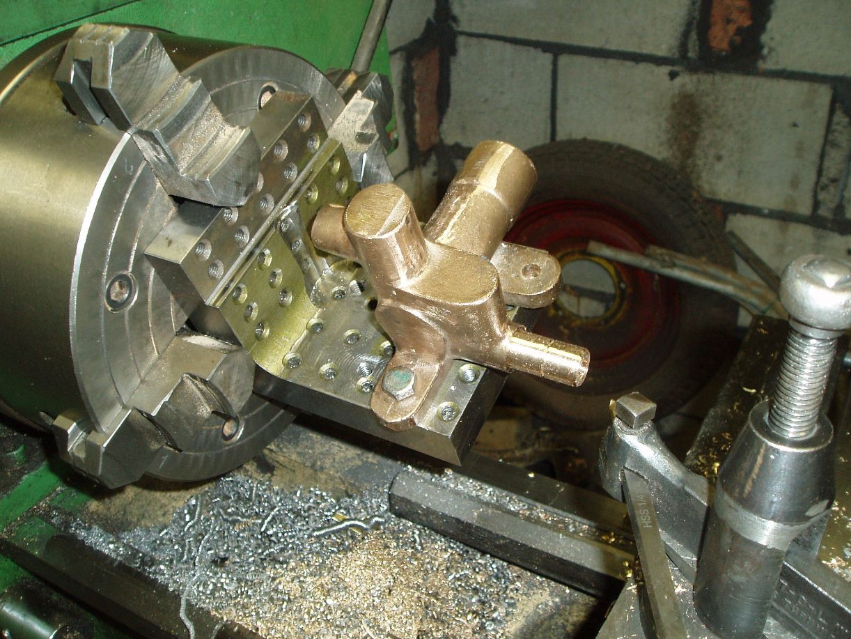
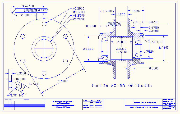
| photoalbum\rolly\axle\4.5 BC Stanley Front hub as machined.jpg |
|
||||||||||||
| photoalbum\rolly\axle\axle assembly-a.jpg | |||||||||||||
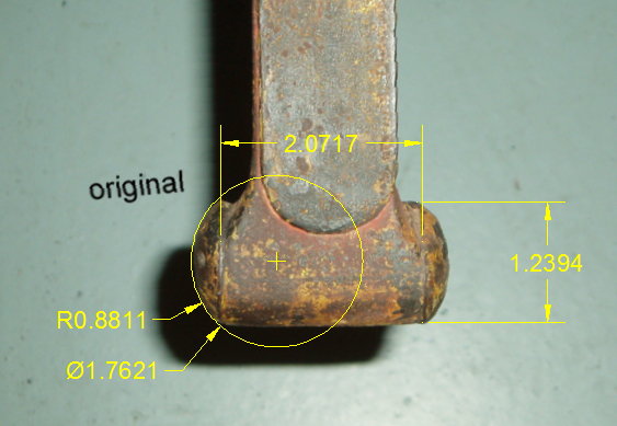
| photoalbum\rolly\axle\axle end.jpg | |||||||||||||
| photoalbum\rolly\axle\Left Spindle.jpg | |||||||||||||
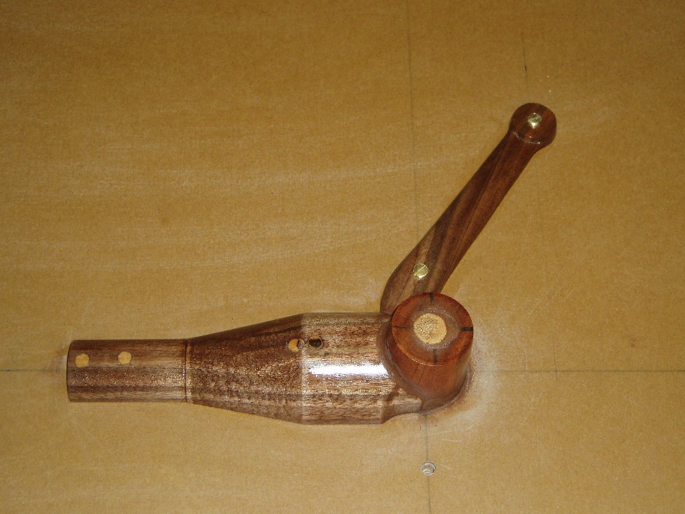
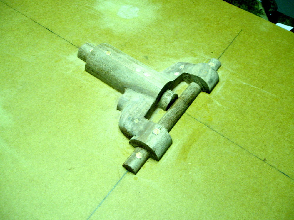
| photoalbum\rolly\axle\Perch pole and spring casting.jpg | |||||||||||||
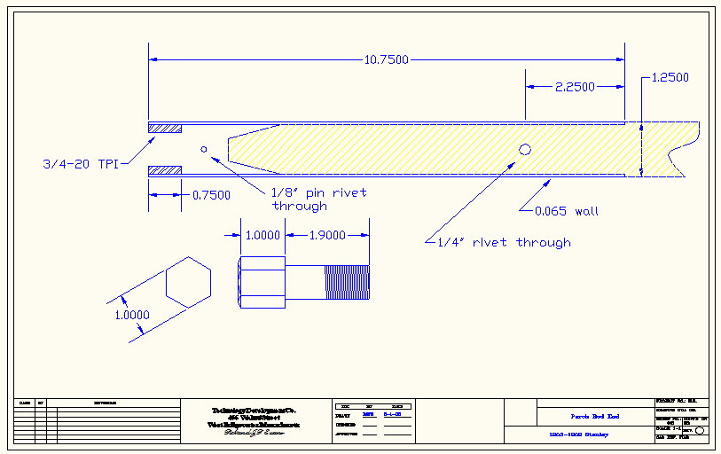
| photoalbum\rolly\axle\Perch rod end.jpg | |||||||||||||
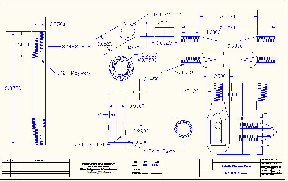
| photoalbum\rolly\axle\Spindle Pin and Parts.jpg | |||||||||||||
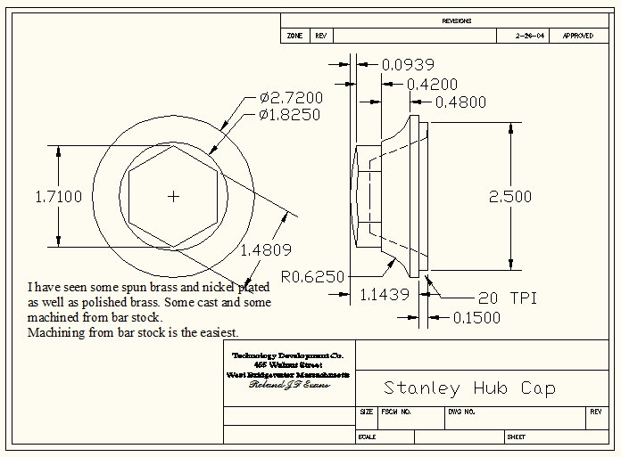
| photoalbum\rolly\axle\Stanley Hub Cap.jpg | |||||||||||||
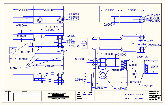
| photoalbum\rolly\axle\Tie rod ends & small parts.jpg | |||||||||||||
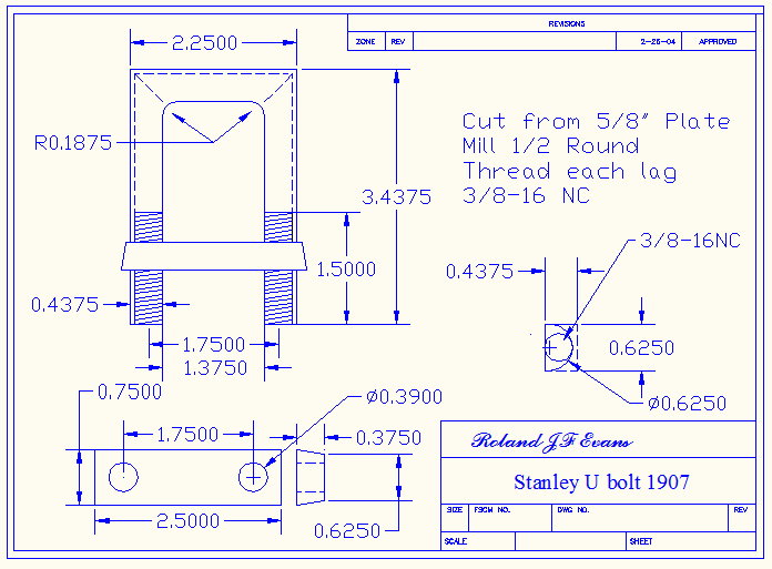
| photoalbum\rolly\axle\U bolt.jpg | |||||||||||||
|
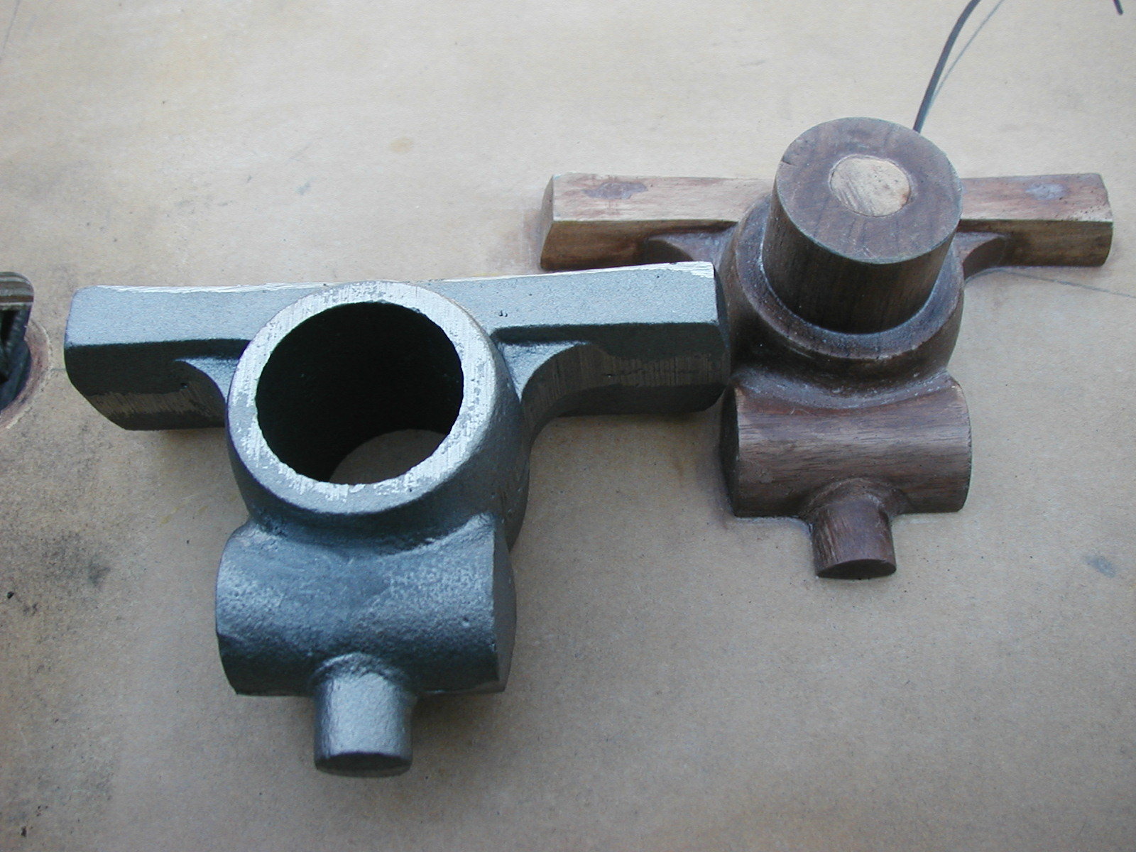
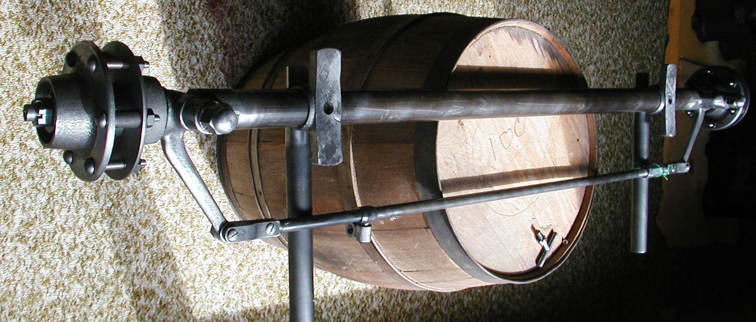
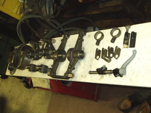
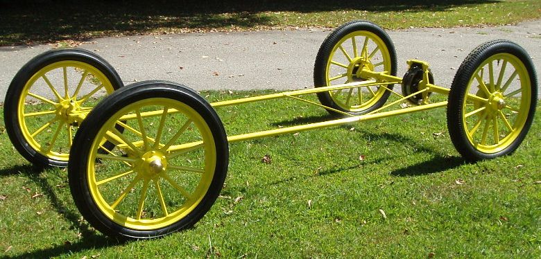
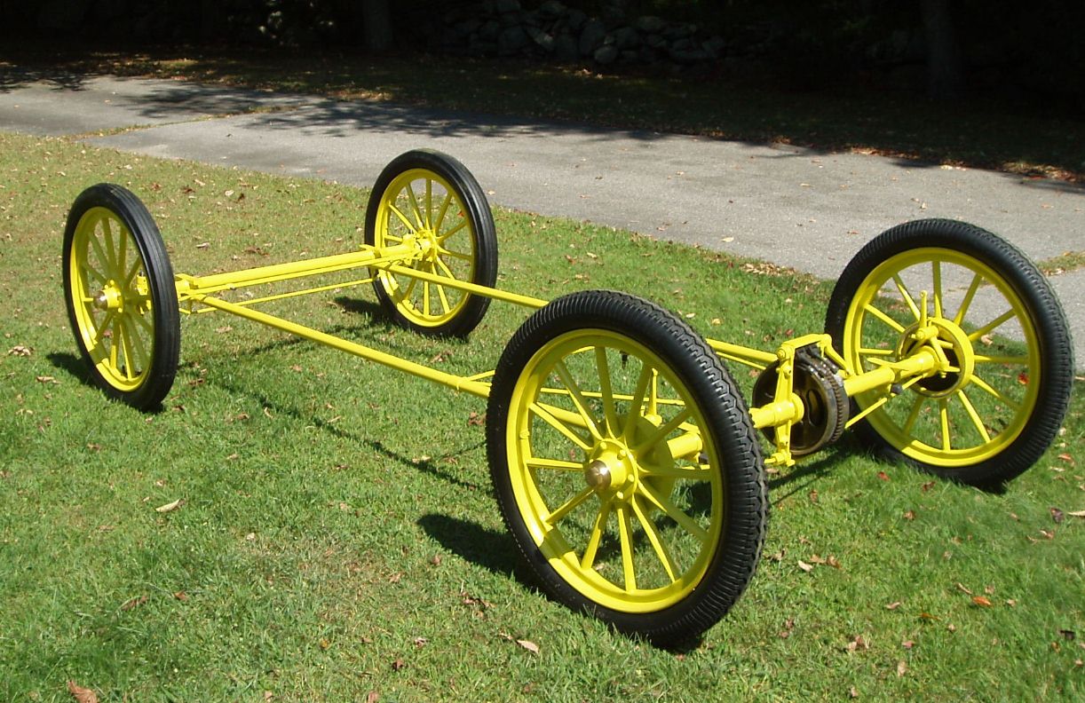
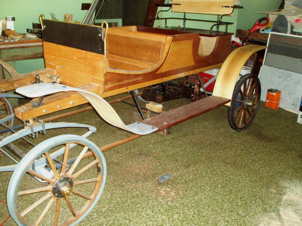
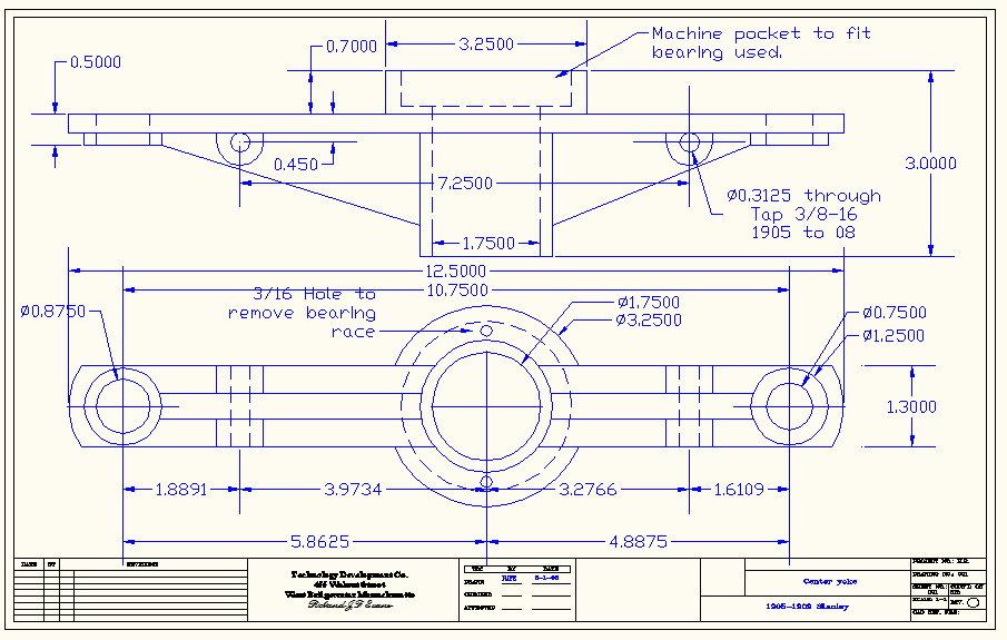
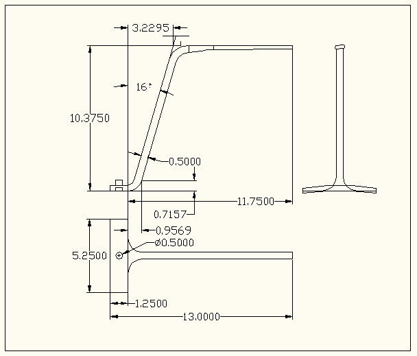
Running Gear |
||||||||||||||||||||
|
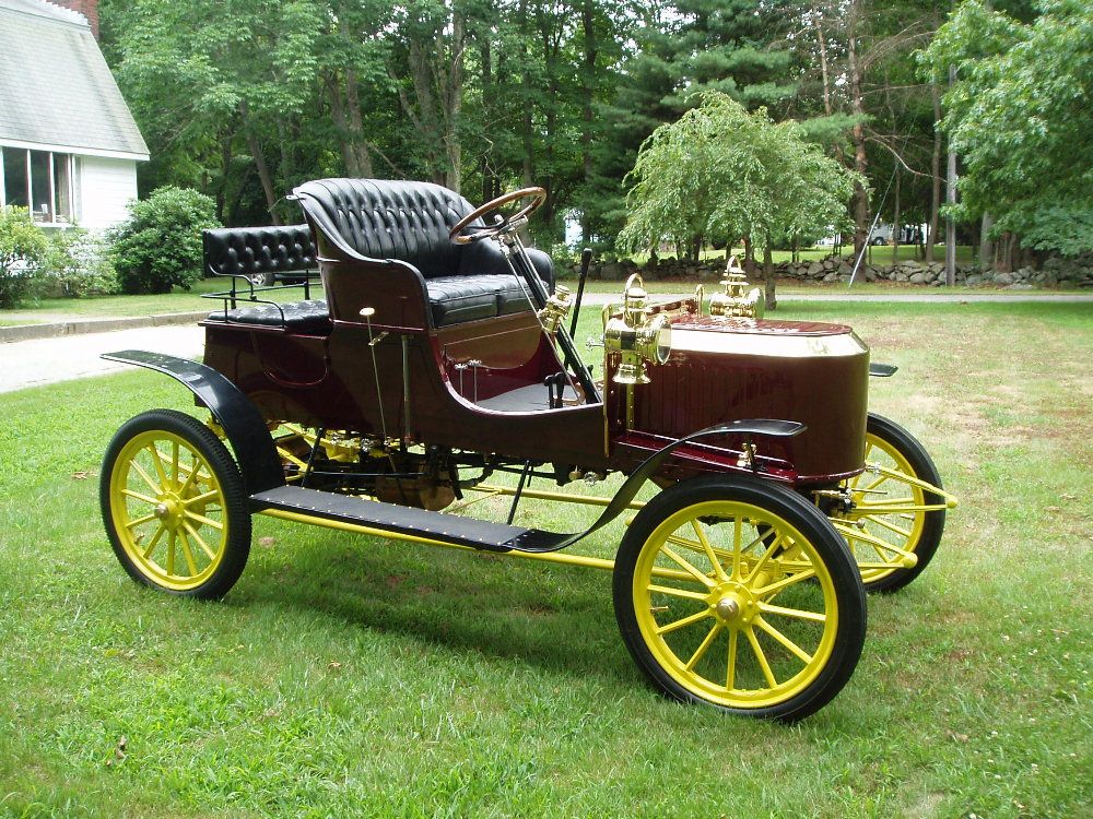
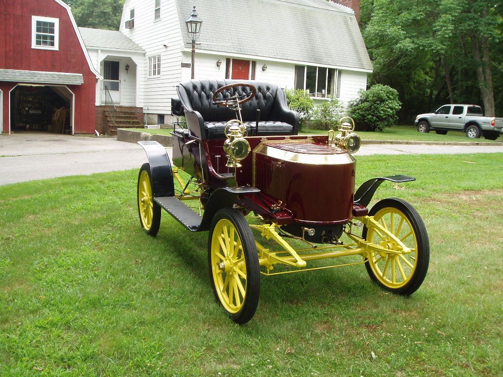
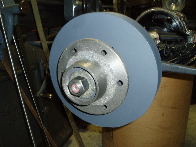
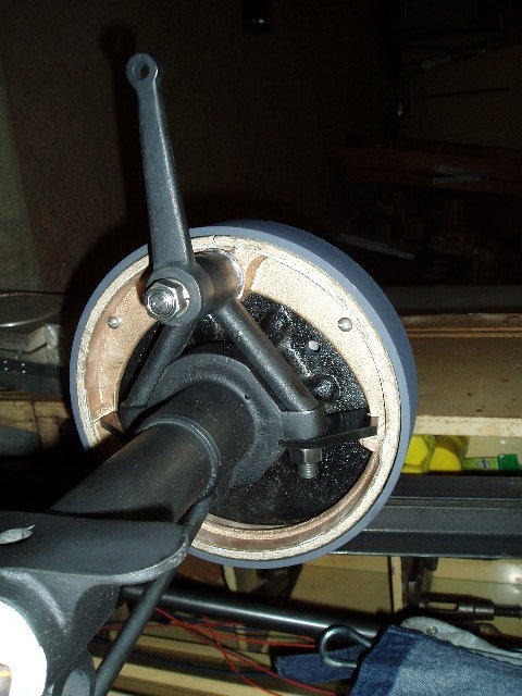
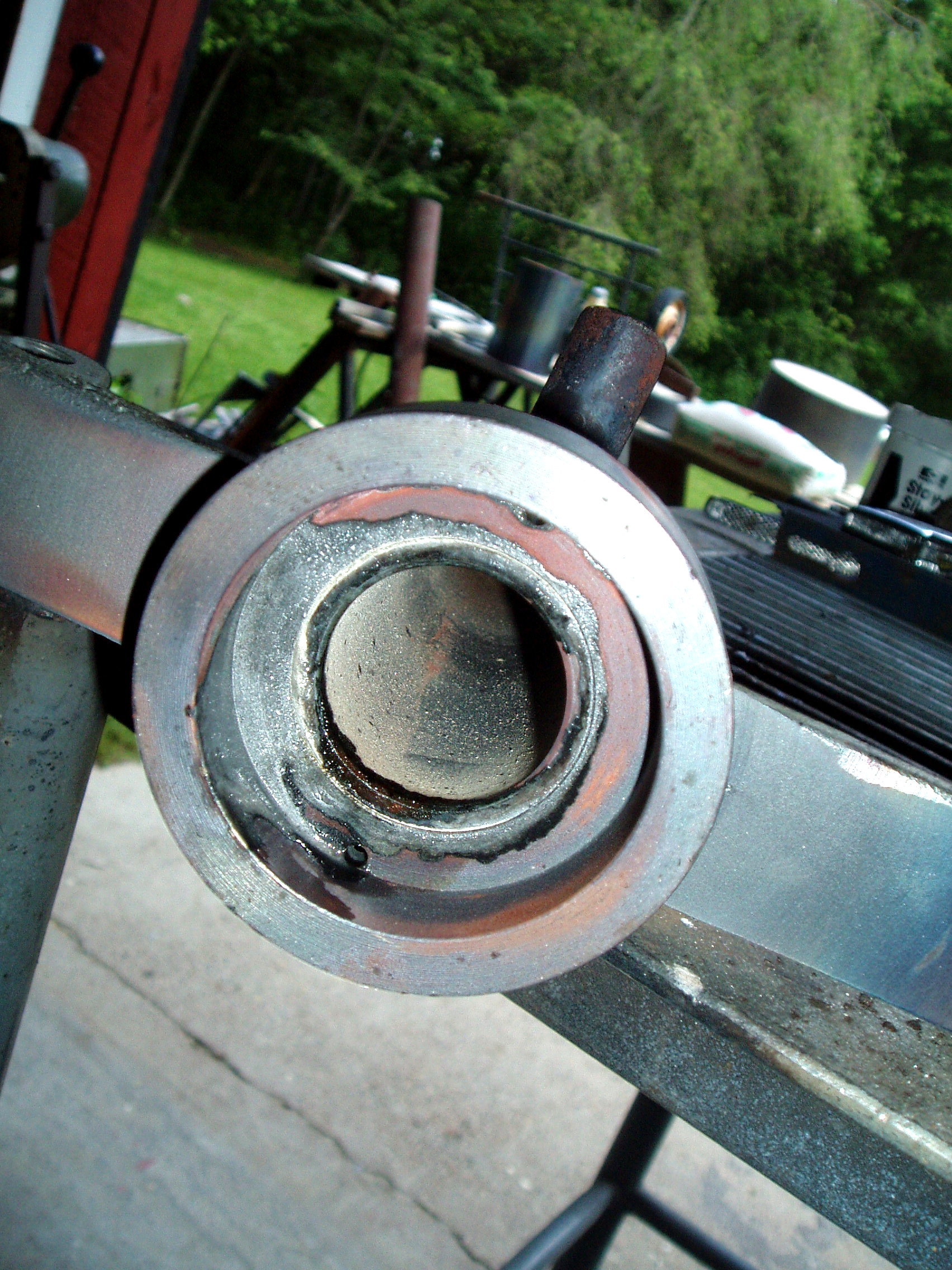
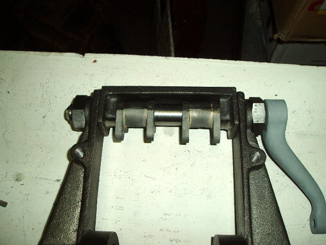
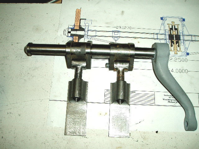
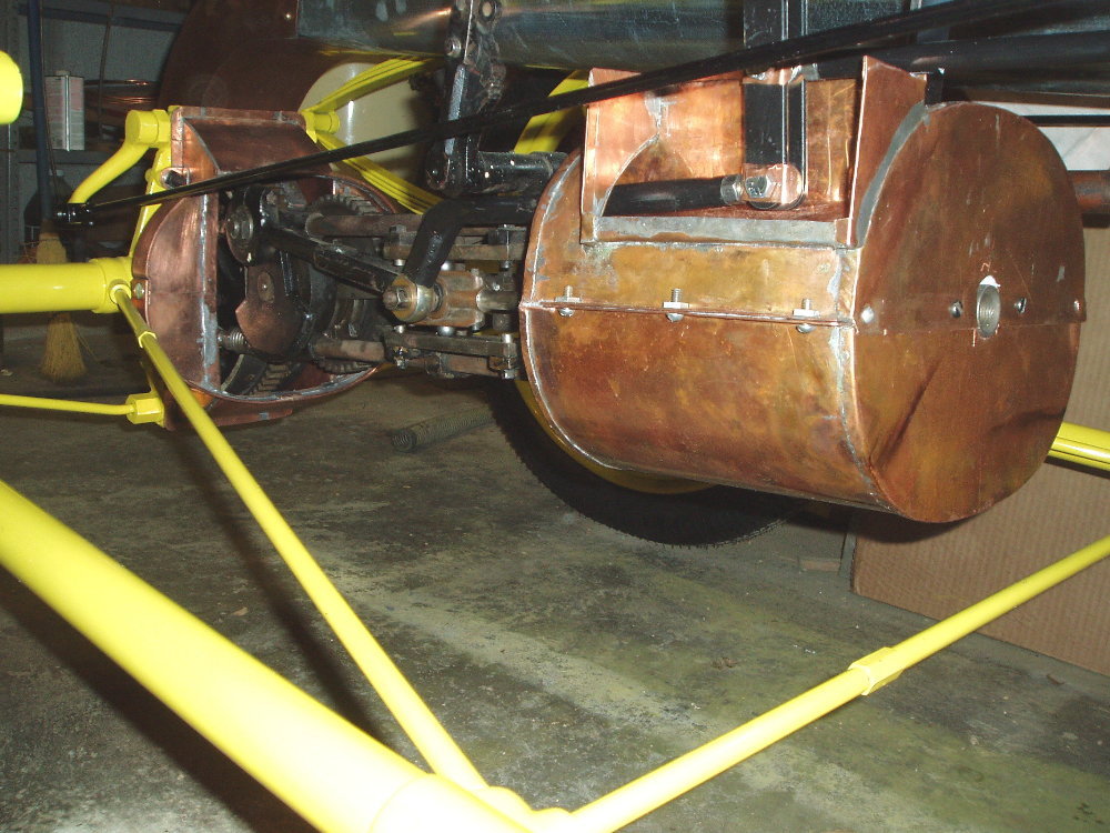
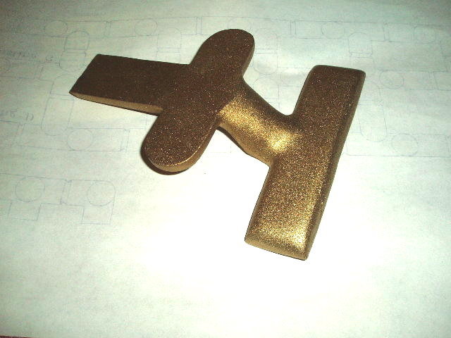
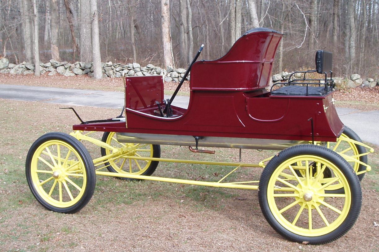
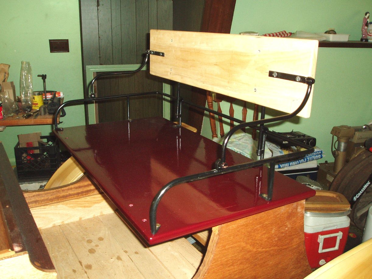
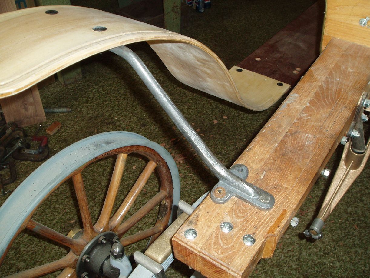
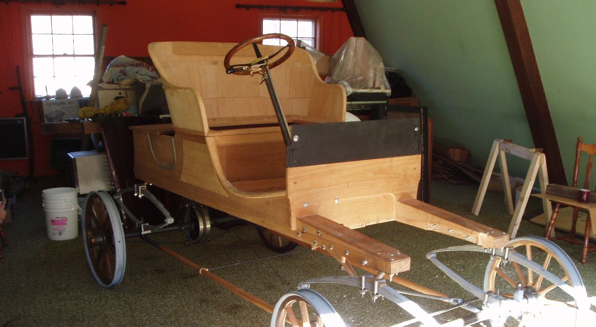
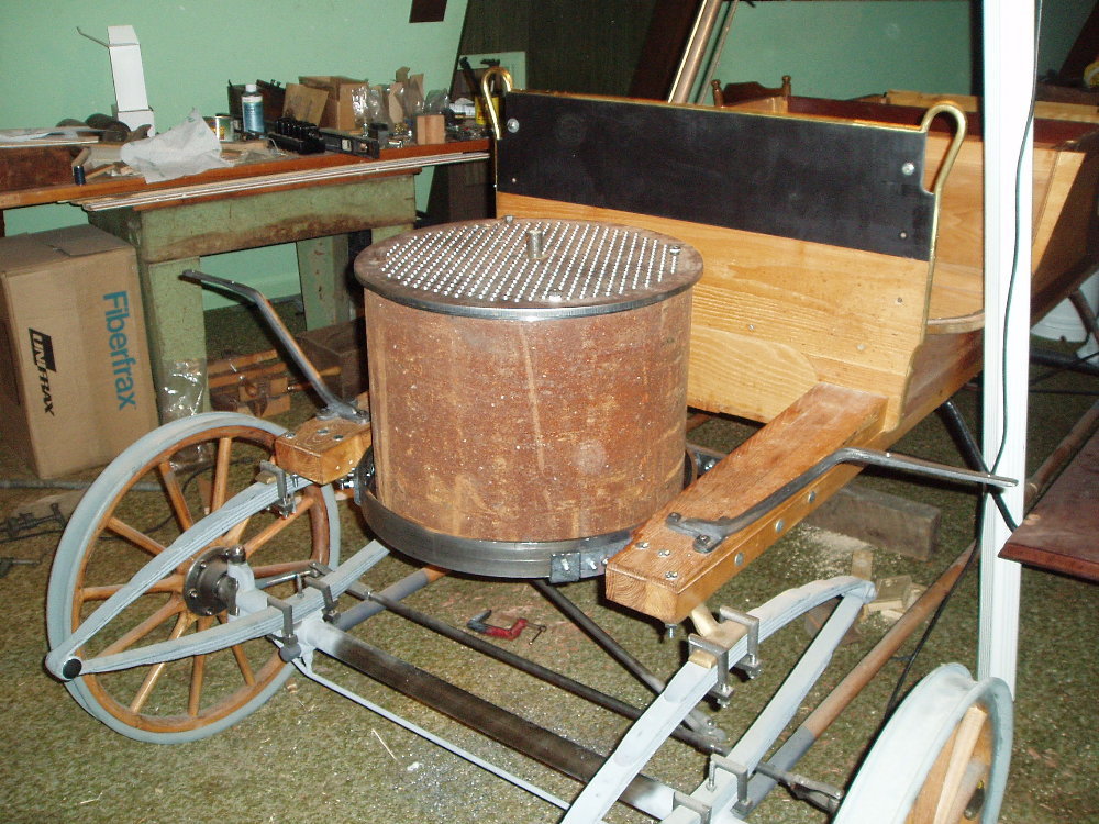
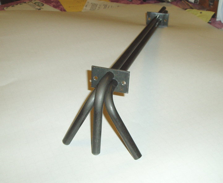
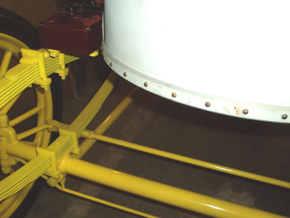
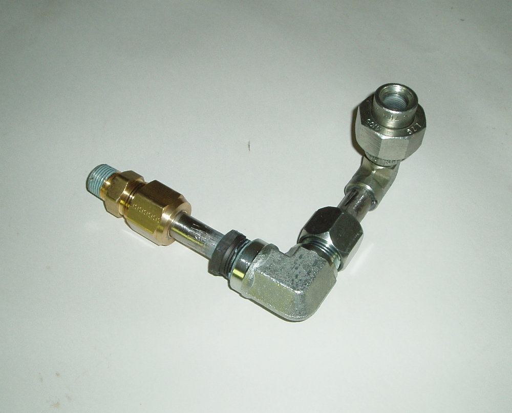
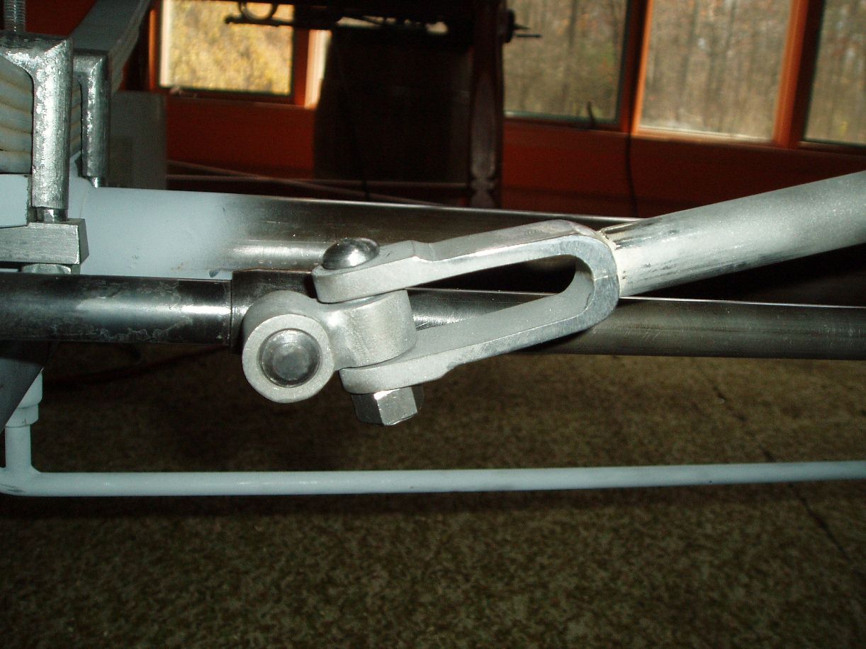
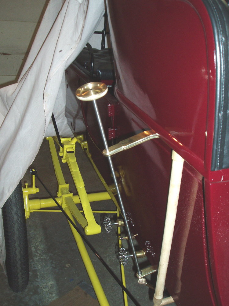
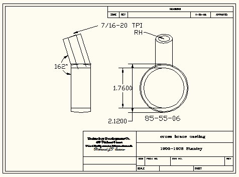
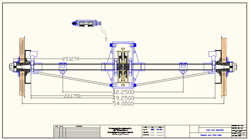
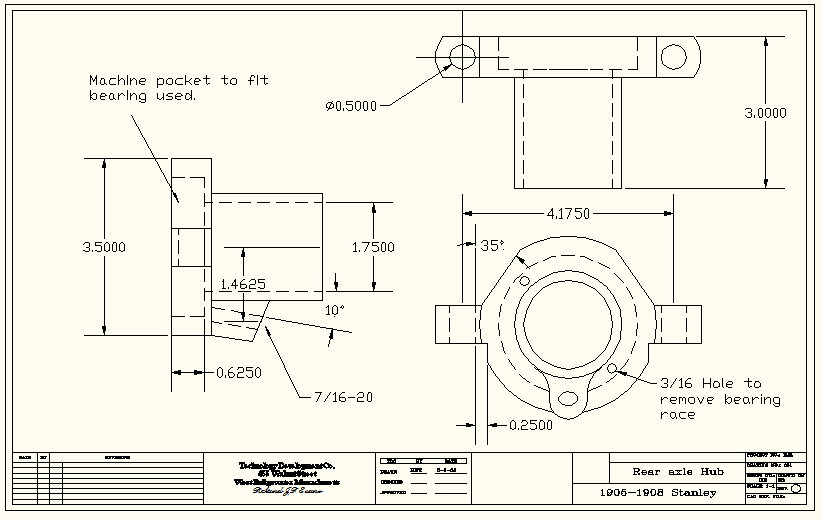
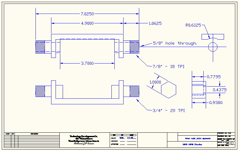
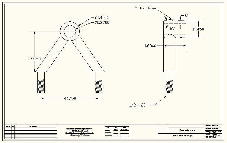
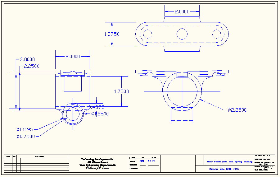
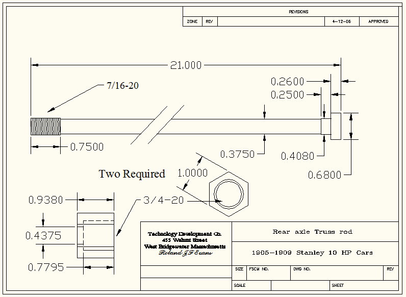
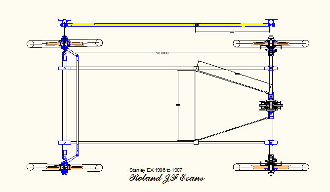
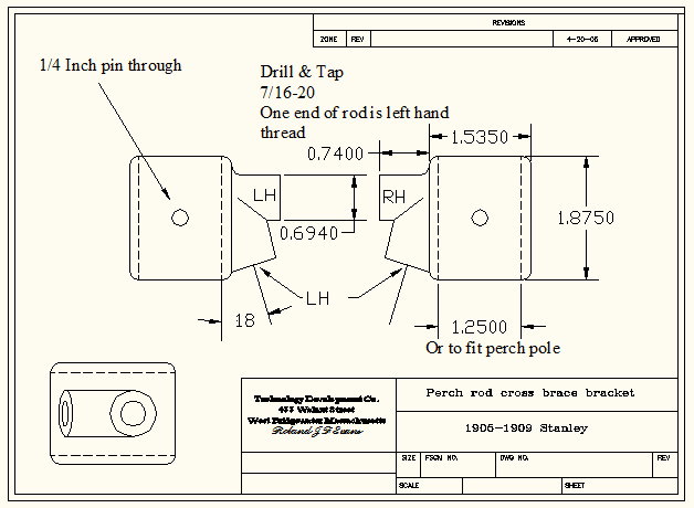
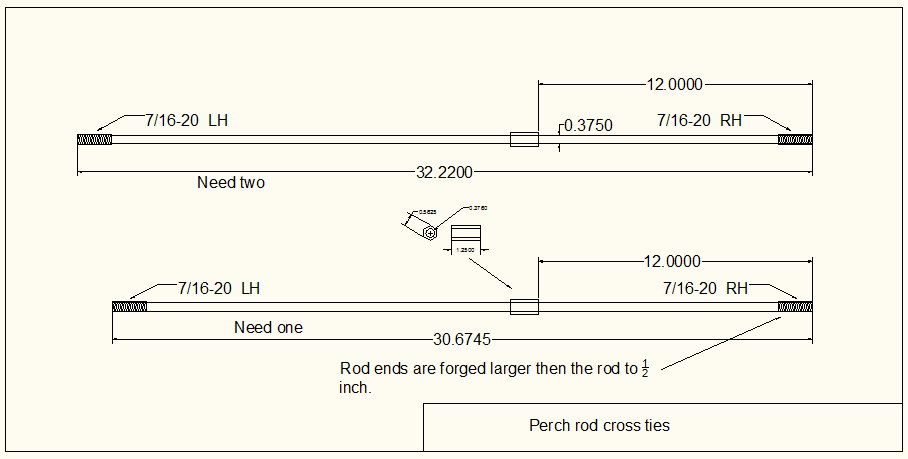
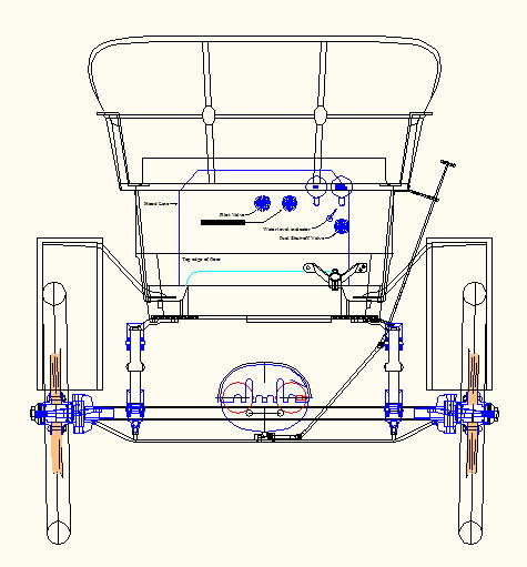
Assembly Assembly of the front and rear end together with the perch rods is quite straightforward. Caution needs to be taken to keep the rear end from bowing. Also keeping the wheels square to each other. The tie rods needed some forging to copy the original. The rods are 3/8-OD with 9/16 hex stock slipped over the rod and silver brazed in place. The ends of the rods are then forged in a die to a larger diameter to ½ inch to enable them to be threaded to 7/16-20 The perch rods I used are hickory as I was lead to believe by others was as the original. Other builder of reproduction Stanley’s are using 4130 steel aircraft tubing. The Yellow paint used was computer matched to old paint on original borrowed drums, it was wet sanded to remove dirt and oxidation. It matched up to John Deere Yellow TY25641. John Deere has six different shades of yellow paint. Other brands also had a match. The wood wheels are original Model EX wheels and needed a lot of epoxy and finish work. New wheels are still available.
|
||||||||||||||||||||
|
CAD Drawings in JPEG |
Click Photos to Enlarge |
|||||||||||||||||||
|
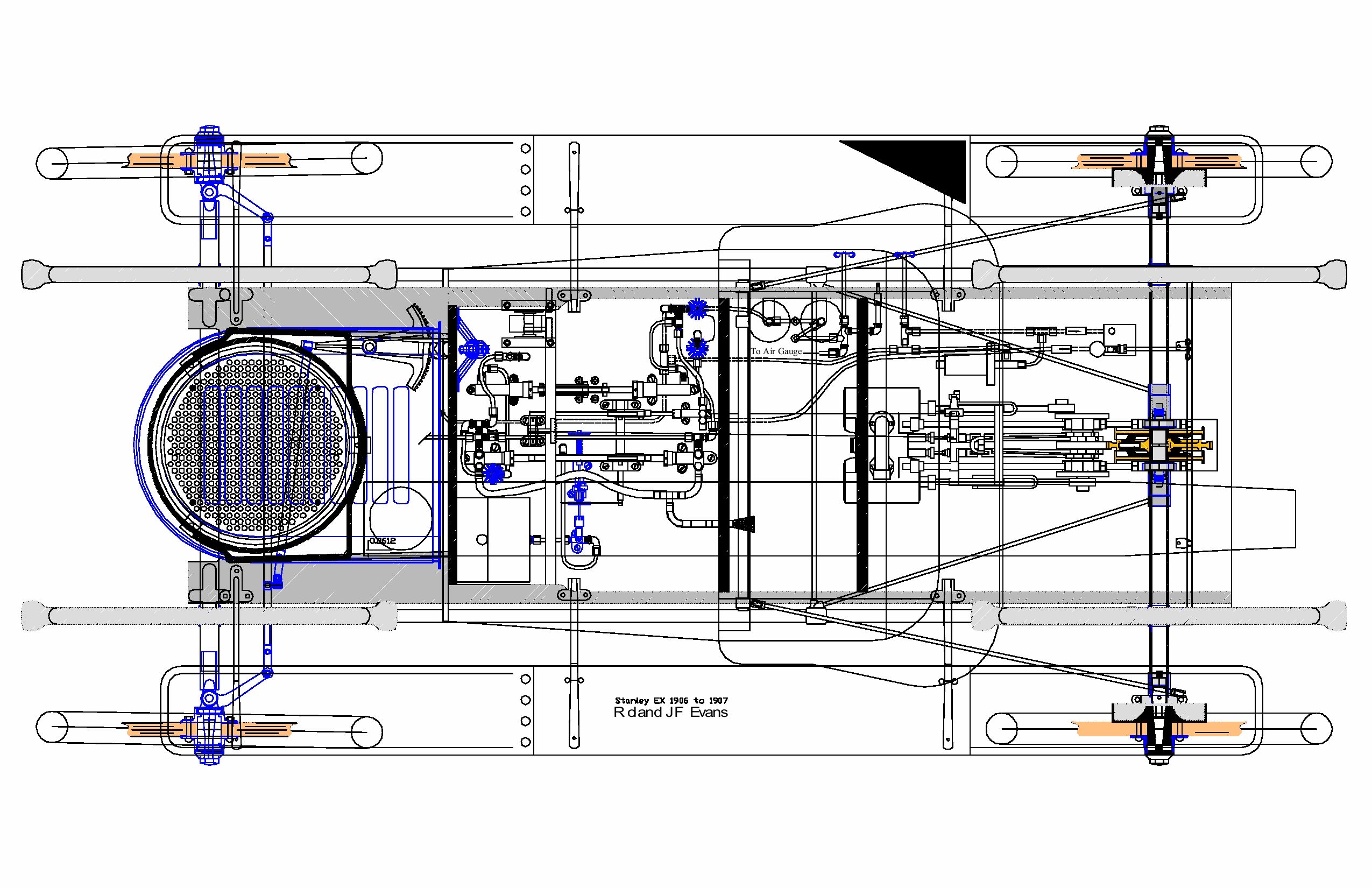
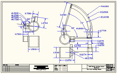
photoalbum\rolly\running gear\EX running gear.jpg photoalbum\rolly\running gear\Perch rod cross brace bracket.jpg photoalbum\rolly\running gear\perch rod cross ties.jpg |
|
|||||||||||||||||||
|
||||||||||||||||||||
|
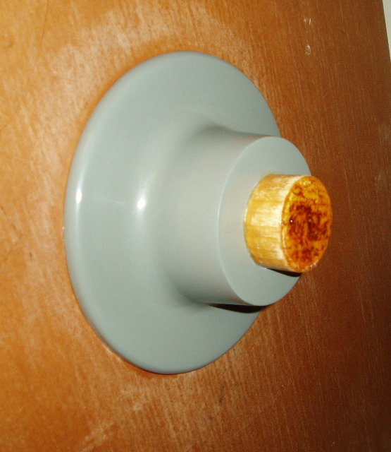
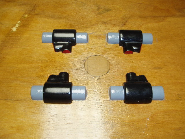
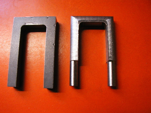
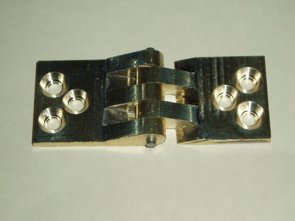
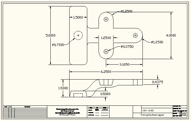
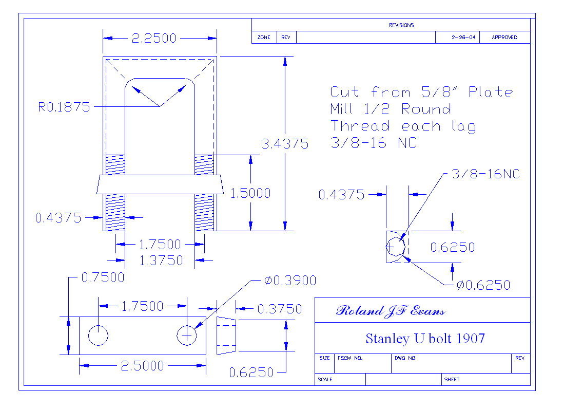
Springs, U-Bolts & Hardware |
|||||||||||||||||
|
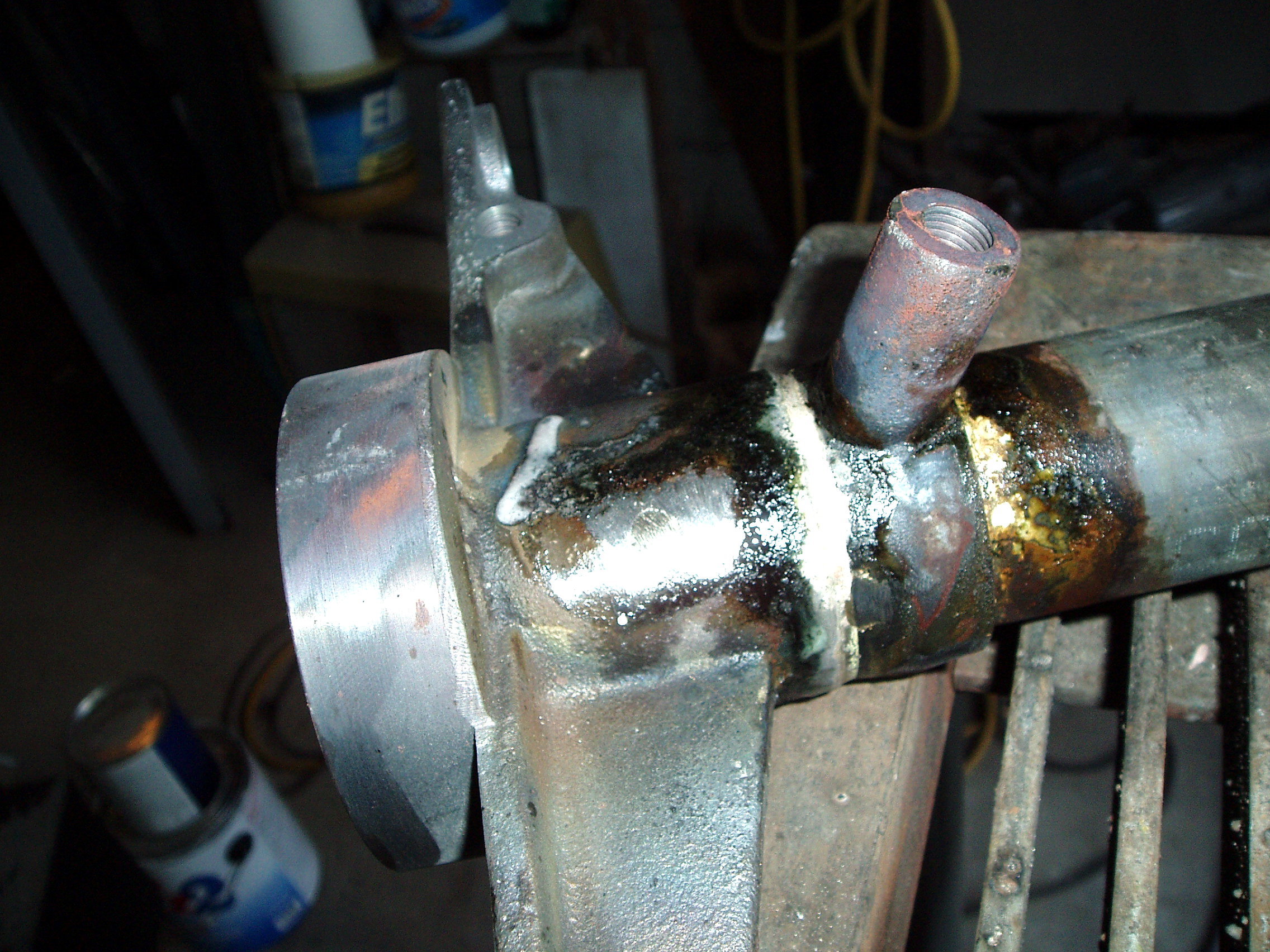
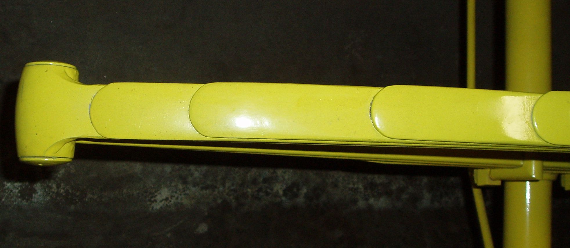
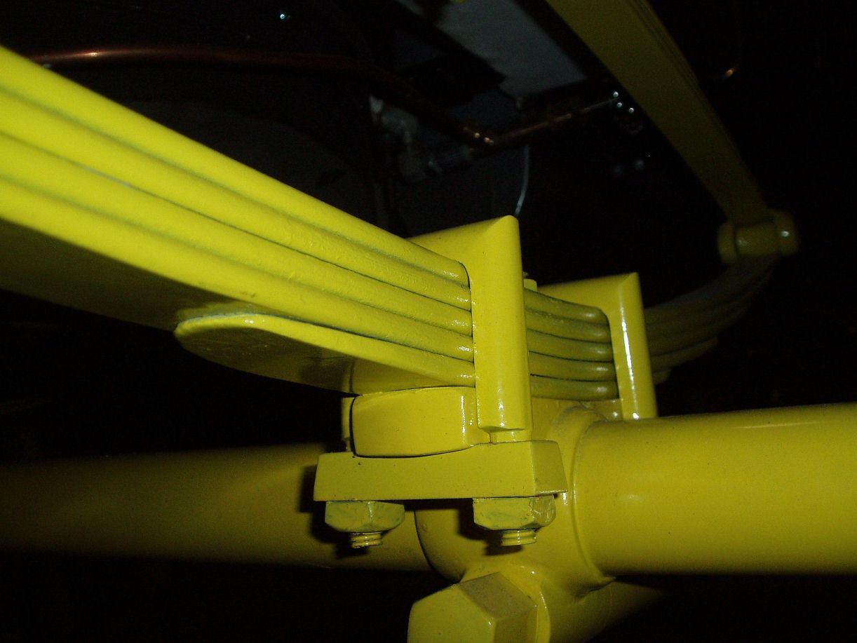
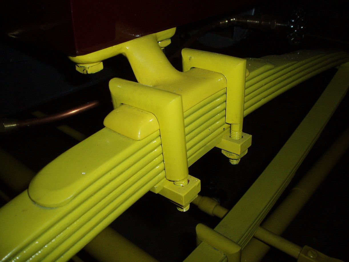
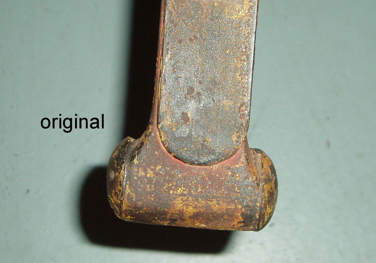
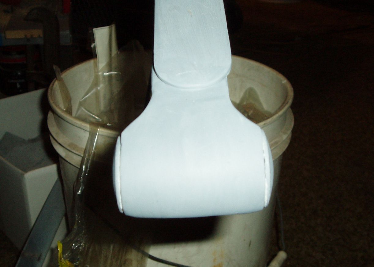
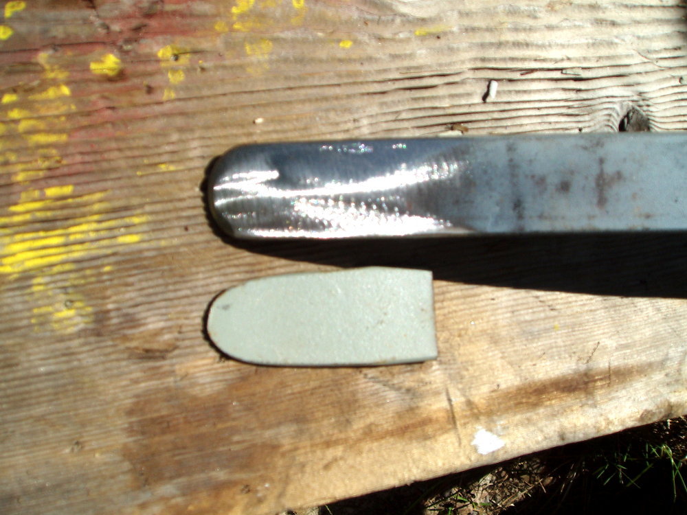
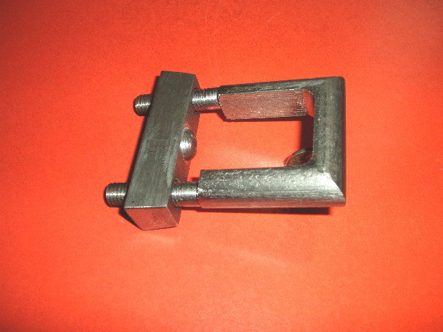
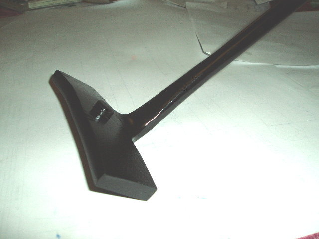
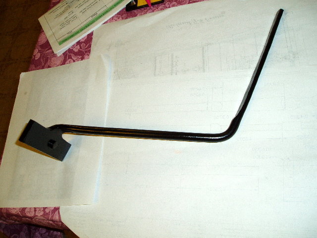
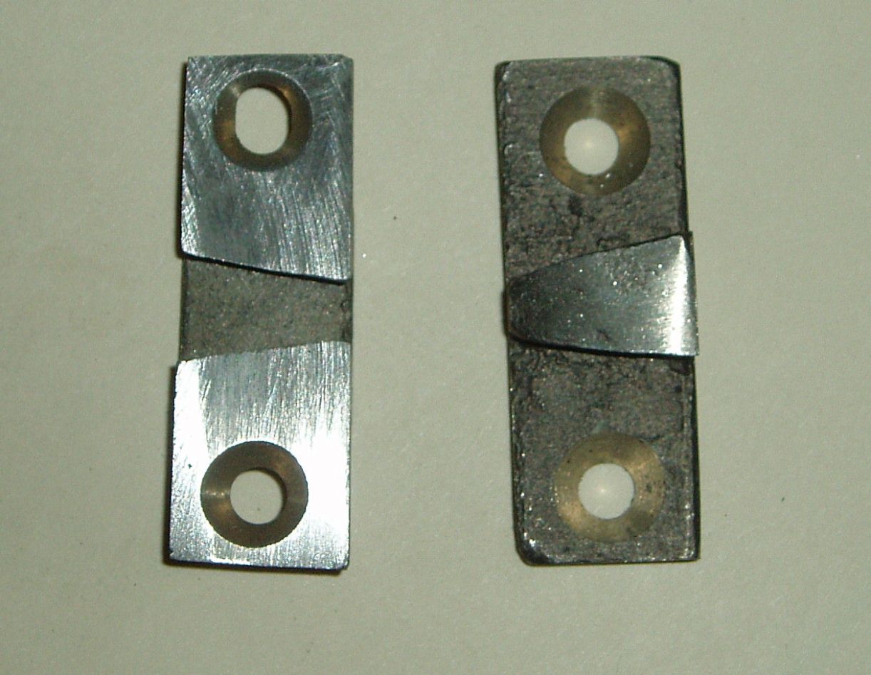
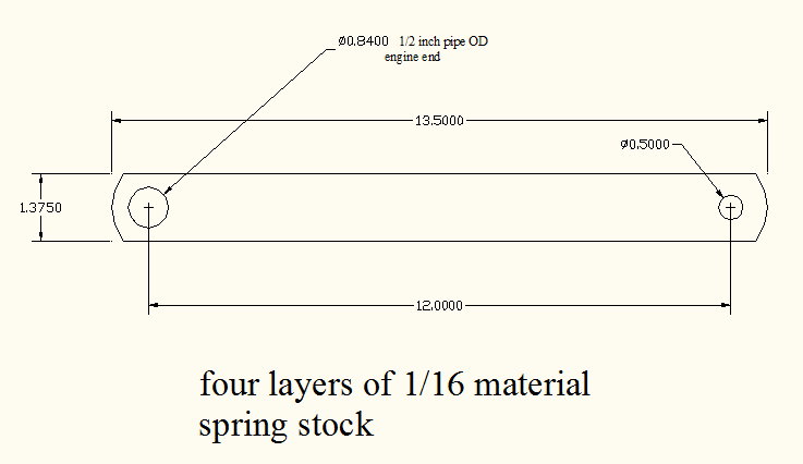
This was a main concern of mine. From all the information I could gather the springs should be 1-3/8 inch’s wide. I was unable to locate any manufacture of springs of this size. 1-1/4 and 1-1/2 were available. I decided on going with the 1-1/4 springs and I would add an extra leaf. The Stanley springs are unique in the shape from what is on the market. Each leaf would have to be re-cut and re-arched. The main spring ends would also have to be reworked to give it the shape of the Stanley end. To do this a thick washer was obtained from the spring supplier with the square hole already punched. These washers had to be welded to each side on both ends and added weld material and grinding was needed to get the desired shape. I ordered six springs so as to have four extra long leafs and some spare leafs if I mess some up in reworking them. Each leaf had tapered ends both in width and thickness and had to have about three inches cut of both ends and reshaped to a round radius and tapered in thickness. Each leaf also had to be re-arched; this was done cold by hand using a template. About six inch in from one end a tab was welded on the underside of each leaf and ground to a little knife edge protruding down. A corresponding groove was ground into the leaf directly under it. This keeps the leaf from moving off to one side. The early cars did not have the tabs on the sides of each leaf. I still need to make new bolts with a larger radius on each end to match the original. This work took a little over a month to
complete. I would not want to do it again. |
|||||||||||||||||
|
CAD Drwaings in JPEG |
Click Photos to Enlarge |
||||||||||||||||
|
photoalbum\rolly\Springs-hardware\Front spring frame support.jpg photoalbum\rolly\Springs-hardware\Rear fender bracket from frabricated part.jpg photoalbum\rolly\Springs-hardware\U-Bolts.jpg |
|
||||||||||||||||
|
|||||||||||||||||
|
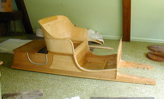
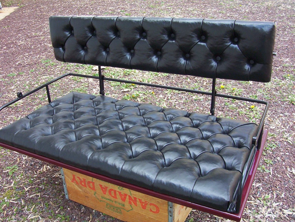
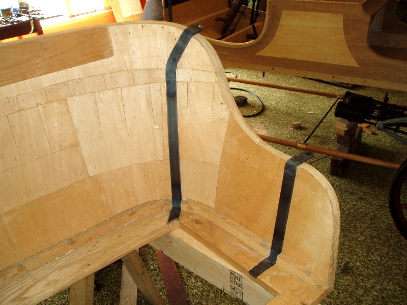
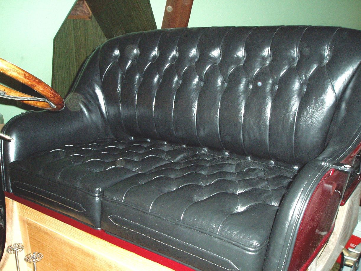
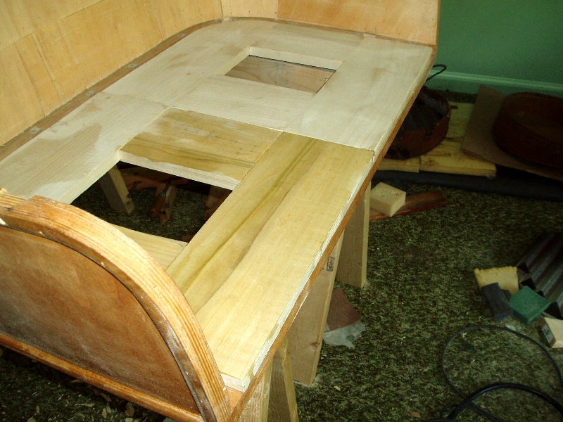
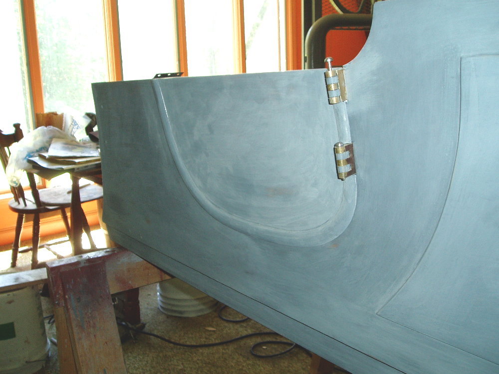
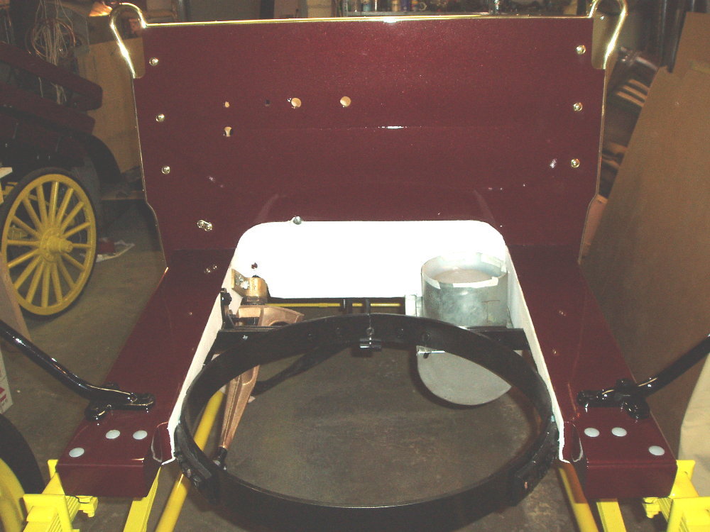
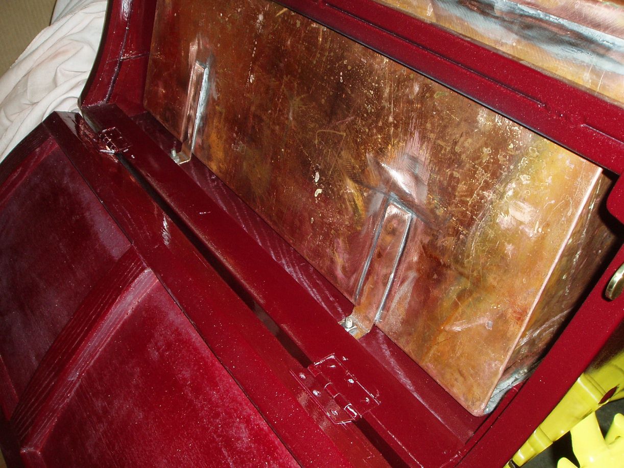
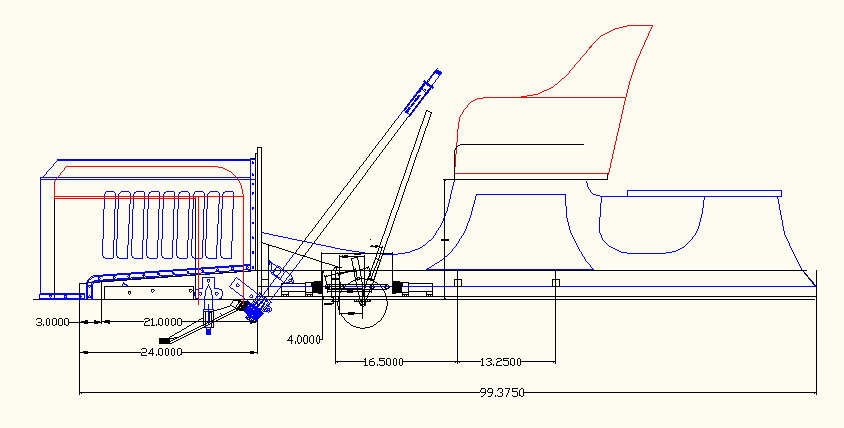
The EX Body |
||||||||||||||||||||||||||
|
||||||||||||||||||||||||||
|
|
||||||||||||||||||||||||||
|
CAD Drawings in JPEG |
Click Photos to Enlarge |
|||||||||||||||||||||||||
|
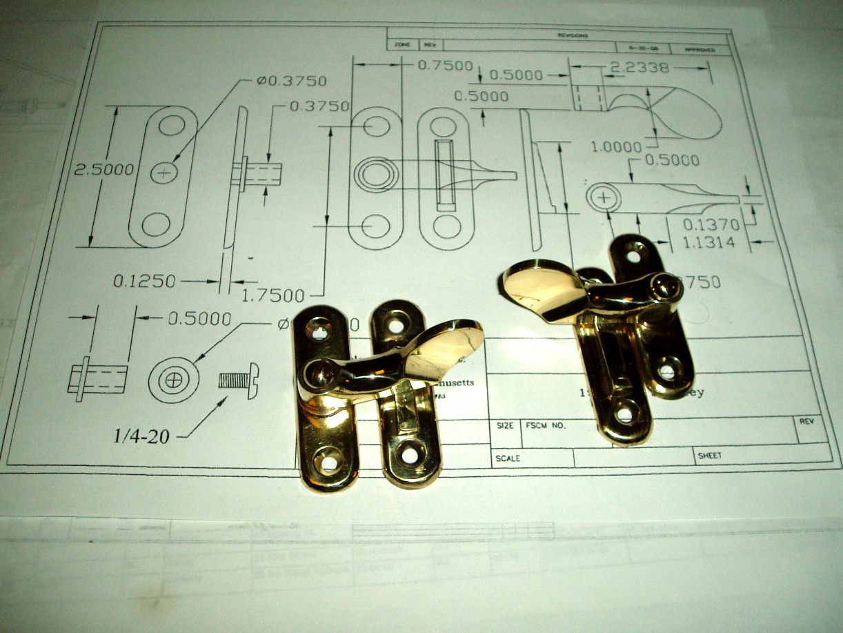
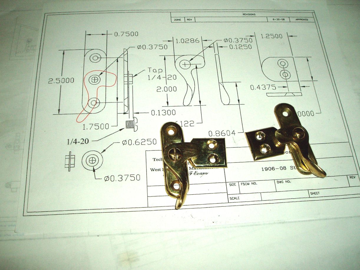
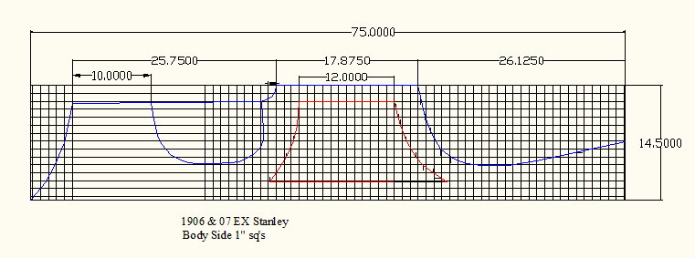
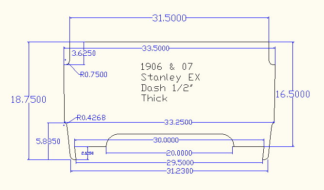
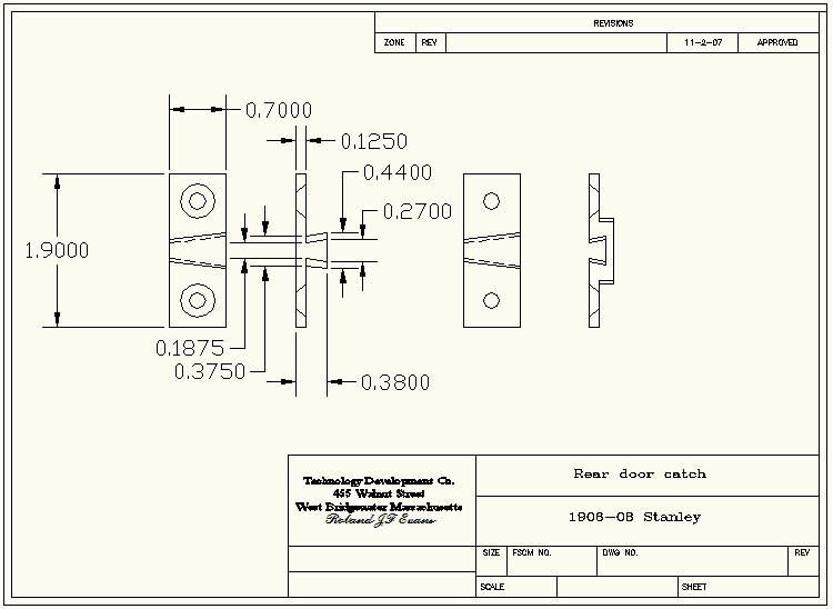
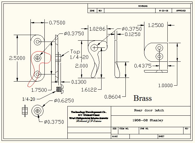
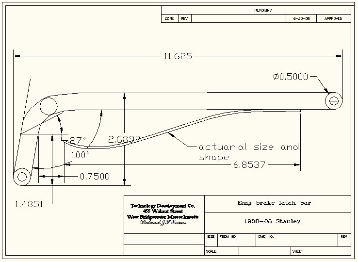
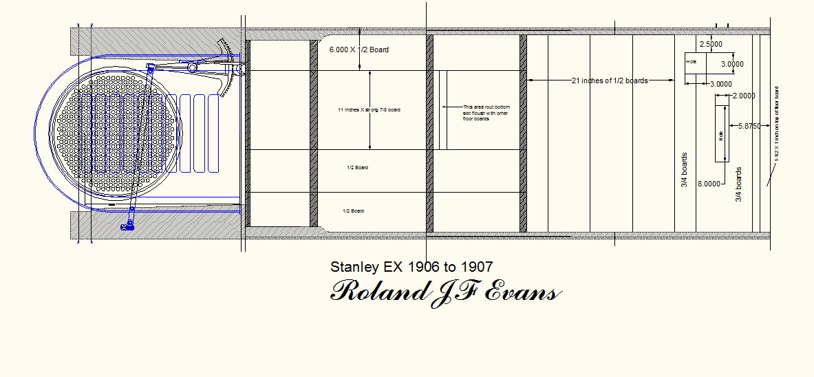
photoalbum\rolly\body\Body
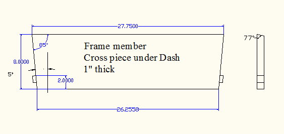
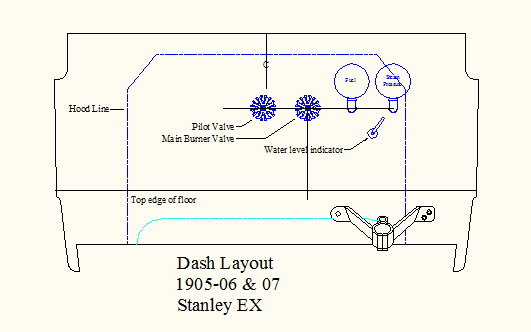
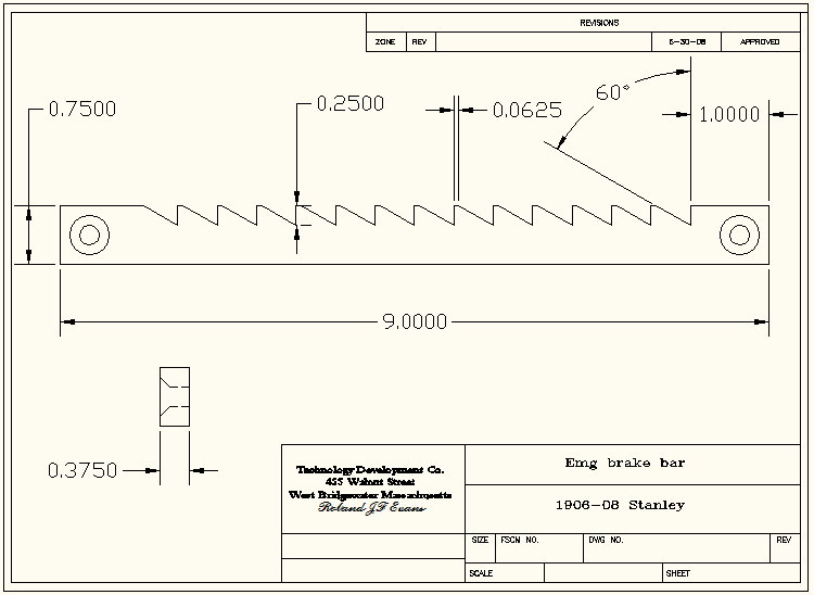
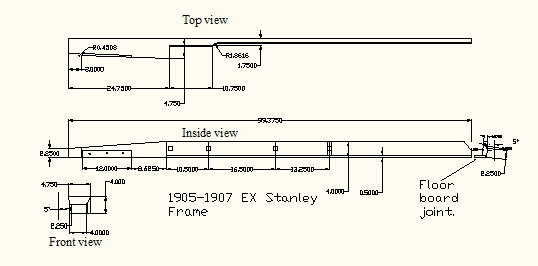
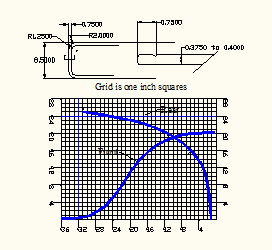
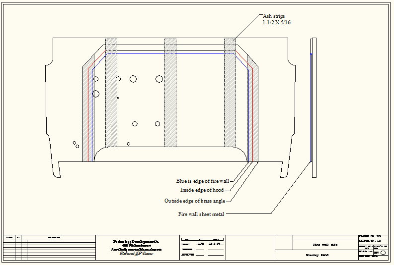
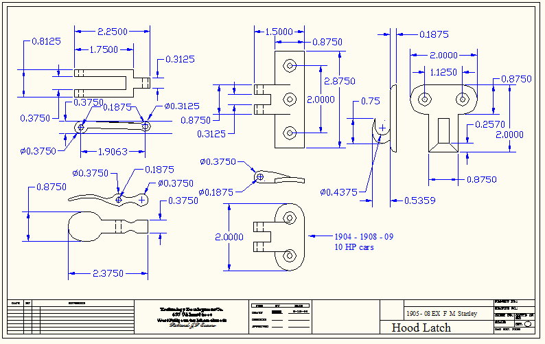
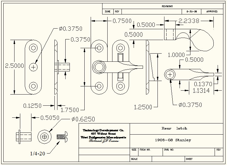
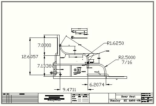
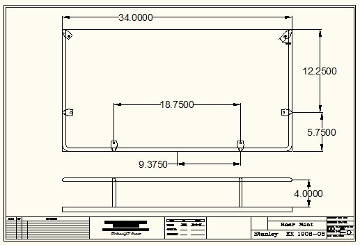
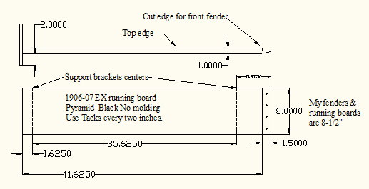
side view.jpg photoalbum\rolly\body\Body side with rear door.jpg photoalbum\rolly\body\buy pass bracket.jpg photoalbum\rolly\body\Cross member under Dash.jpg photoalbum\rolly\body\Dash layout-05-07.jpg photoalbum\rolly\body\Dash.jpgphotoalbum\rolly\body\door catch.jpg photoalbum\rolly\body\door latch.jpg photoalbum\rolly\body\Emg brake latch bar.jpg photoalbum\rolly\body\Emg brake bar-1.jpg photoalbum\rolly\body\EX Frame flooring.jpg photoalbum\rolly\body\EX Frame only.jpgphotoalbum\rolly\body\Fenders.jpg photoalbum\rolly\body\Fire wall side.jpgphotoalbum\rolly\body\Hood latch -2.jpg photoalbum\rolly\body\Rear door.jpgphotoalbum\rolly\body\Rear latch.jpg photoalbum\rolly\body\Rear seat hardware.jpgphotoalbum\rolly\body\Rear seat hardware-2.jpg photoalbum\rolly\body\Running board.jpg |
|
|||||||||||||||||||||||||
|
||||||||||||||||||||||||||
|
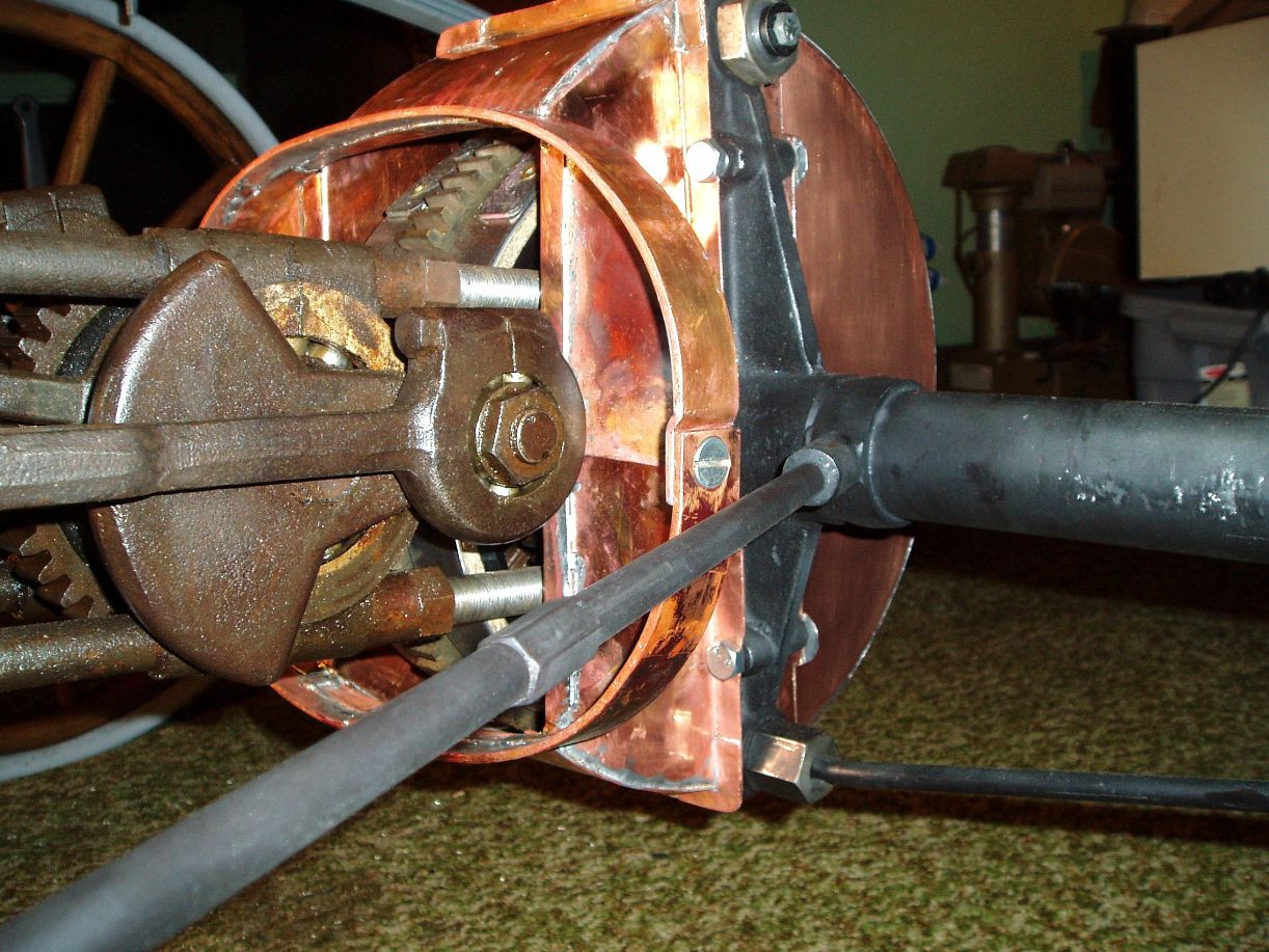
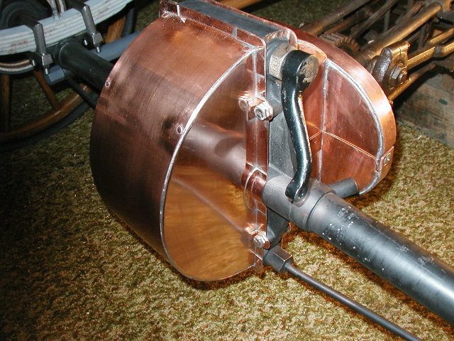
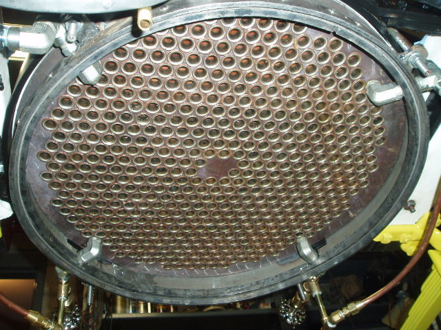
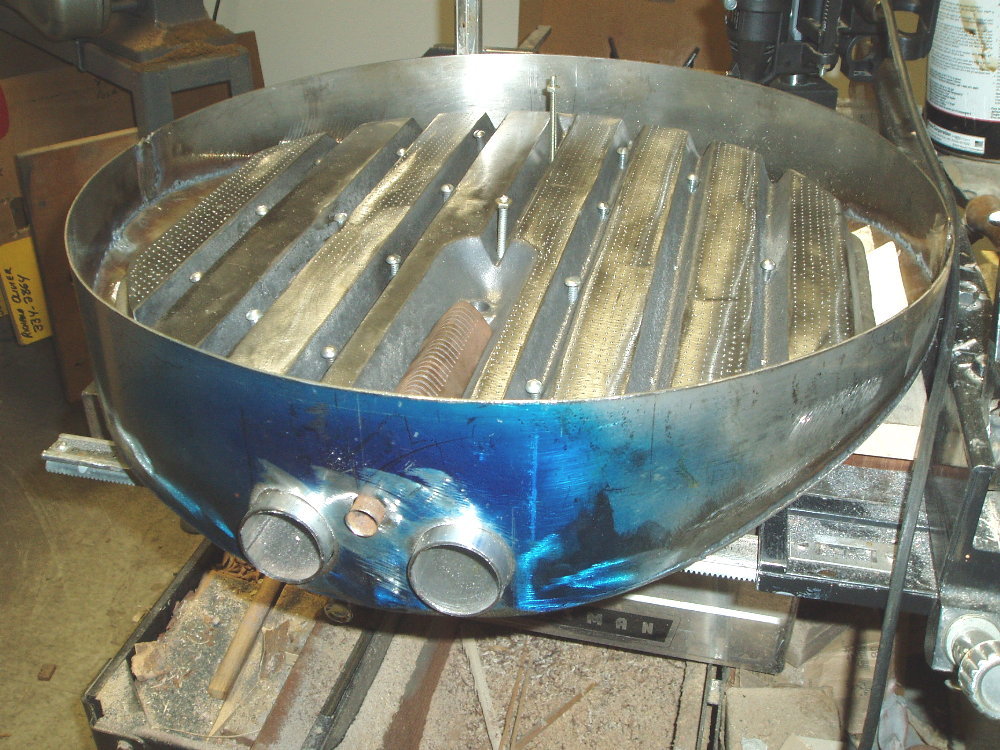
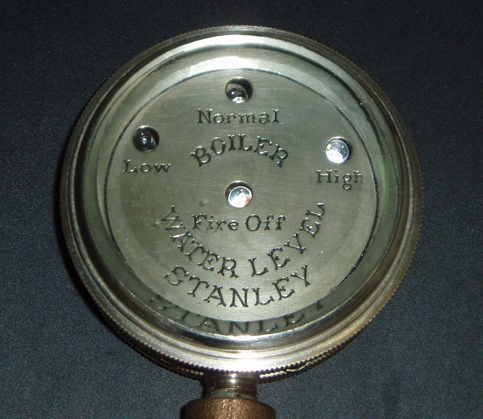
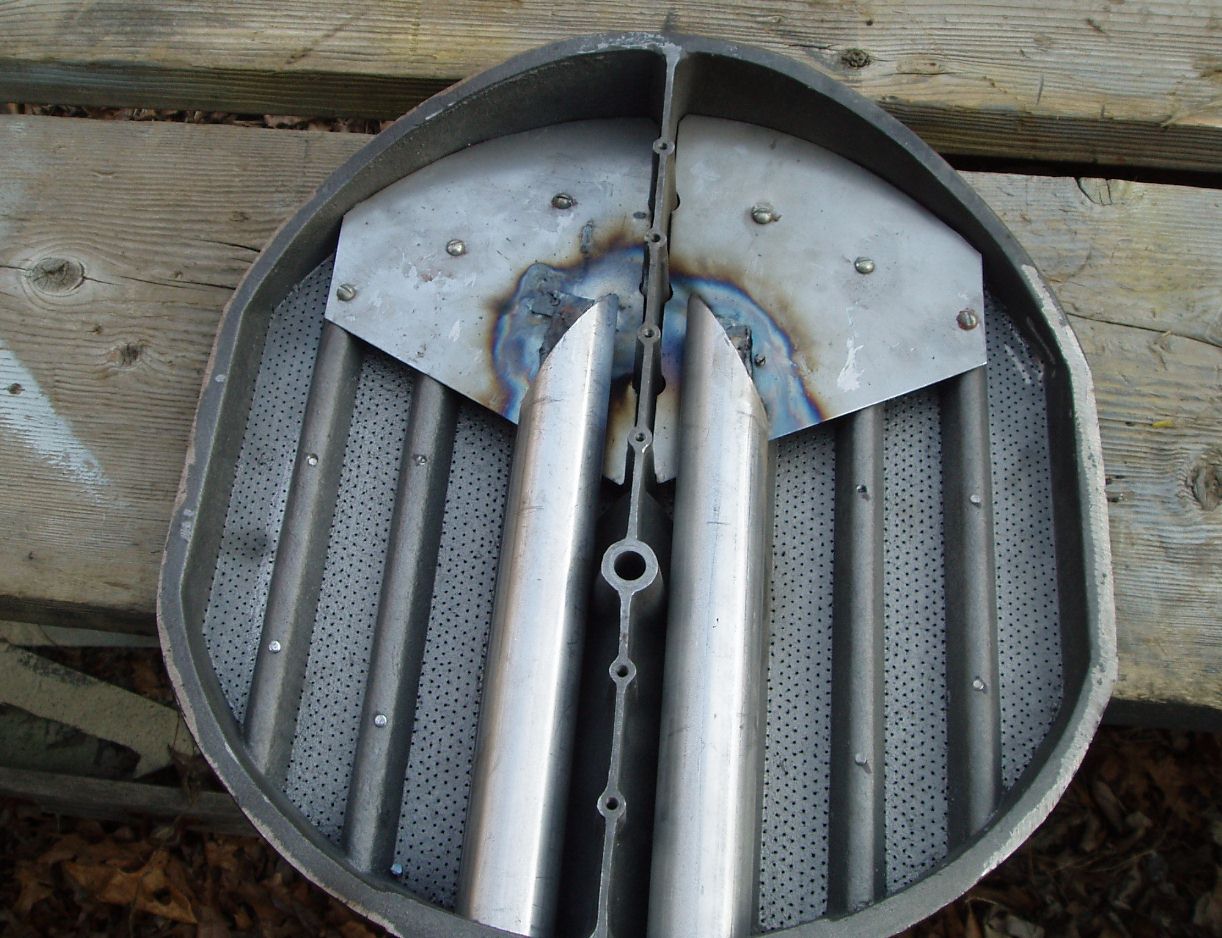
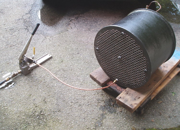
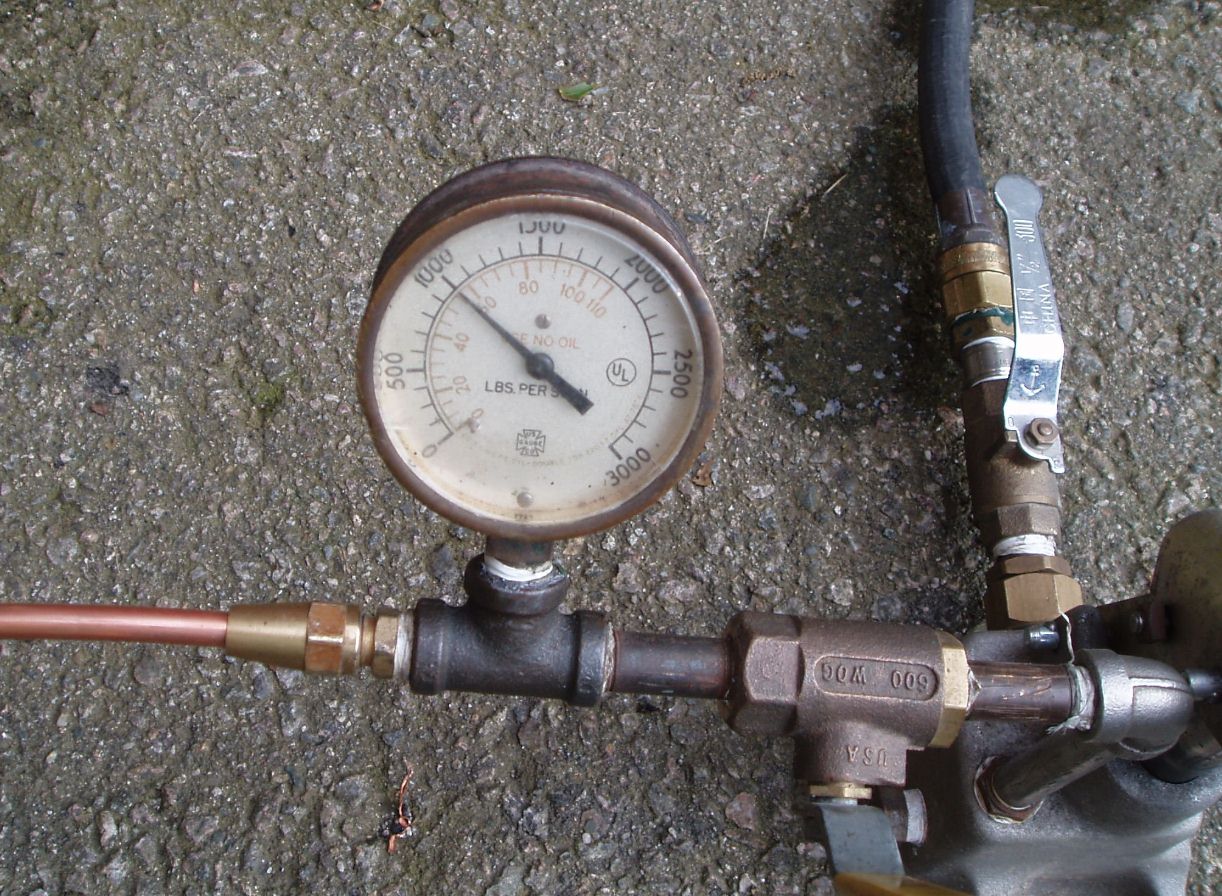
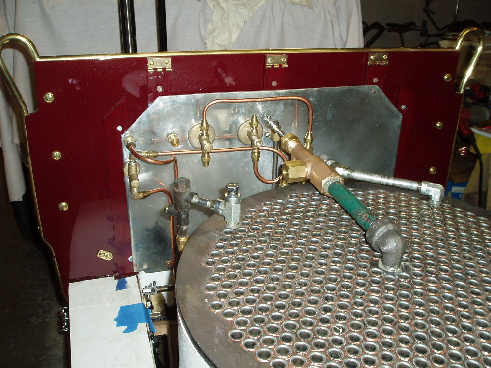
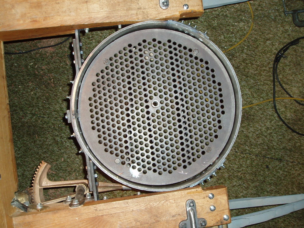
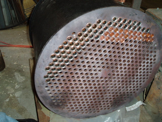
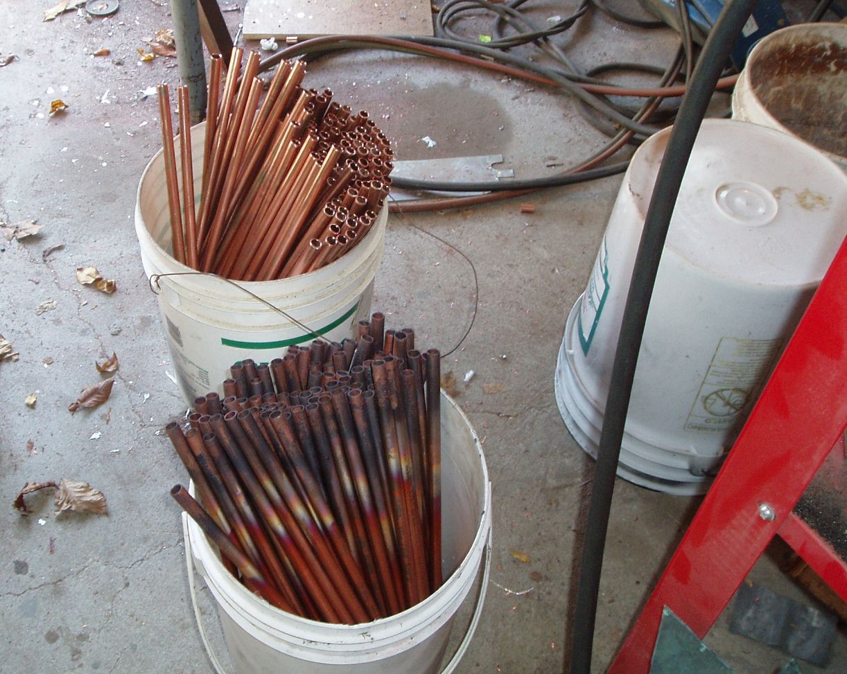
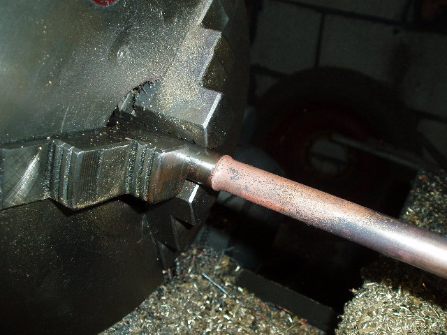
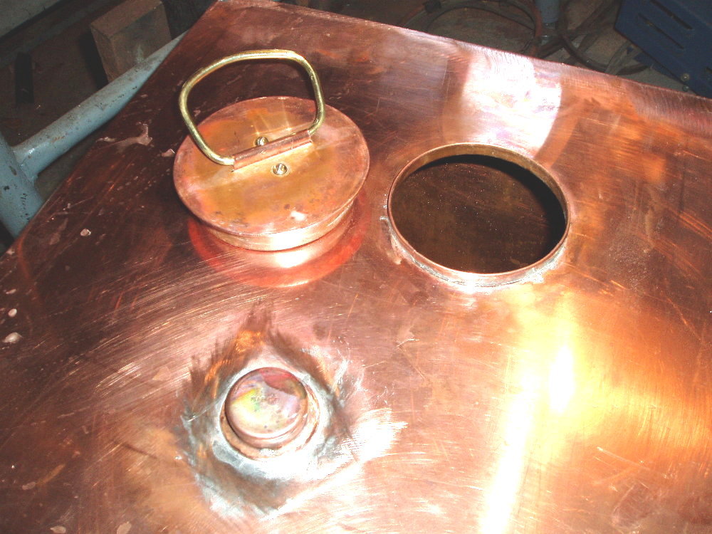
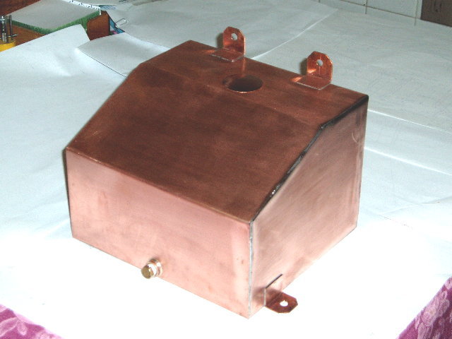
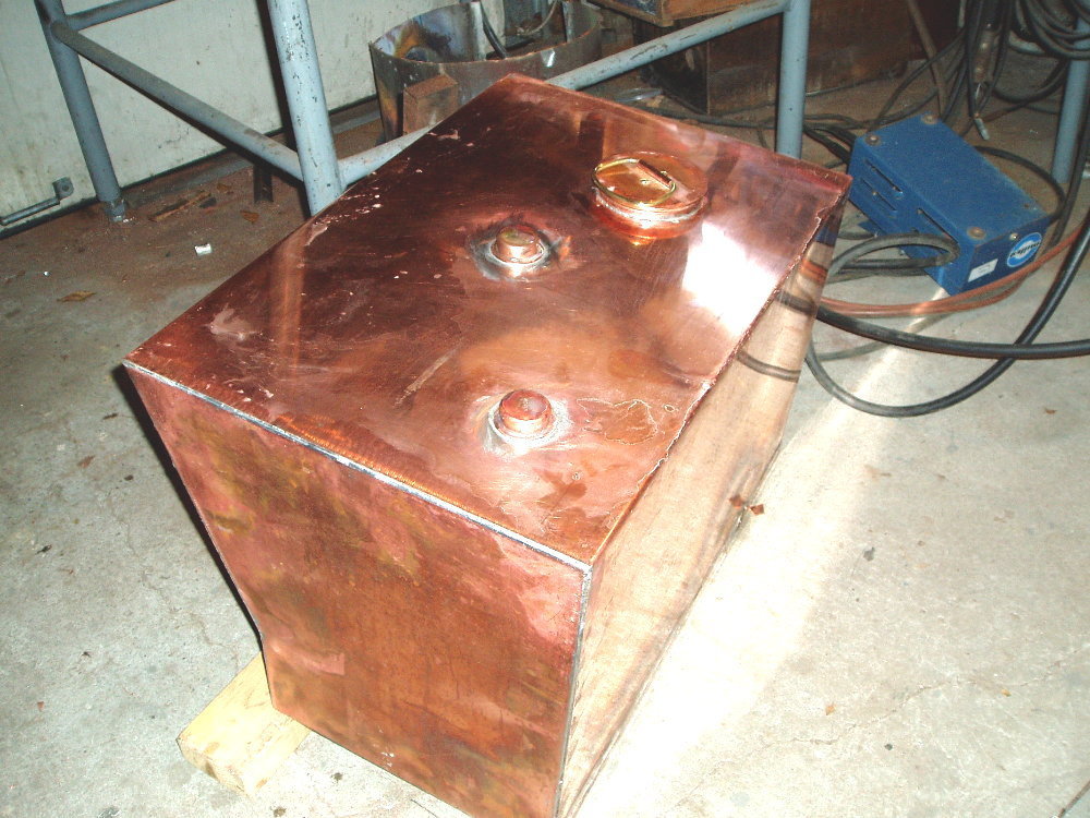
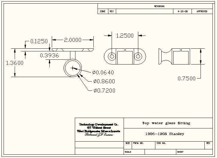
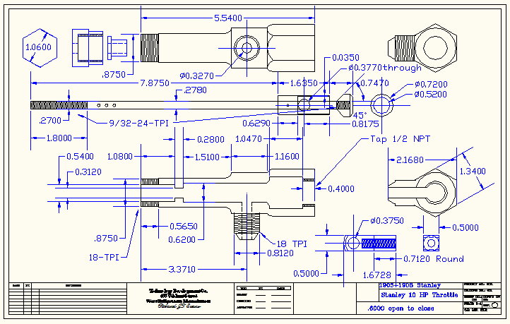
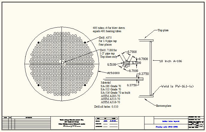
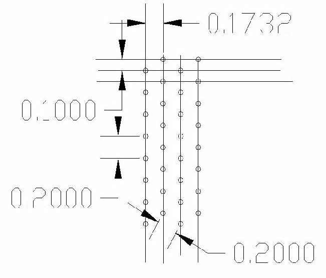
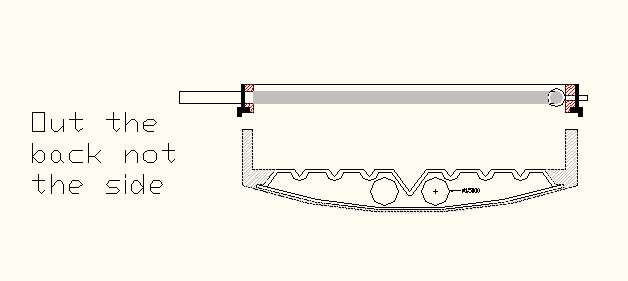
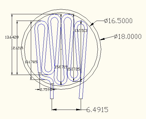
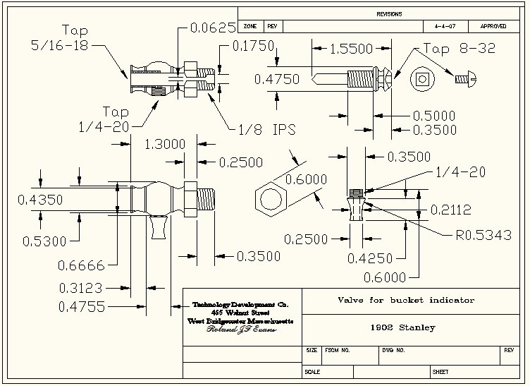
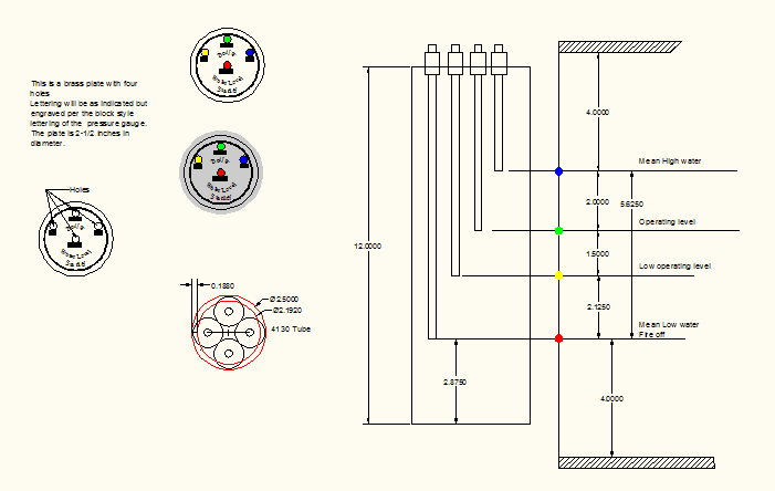
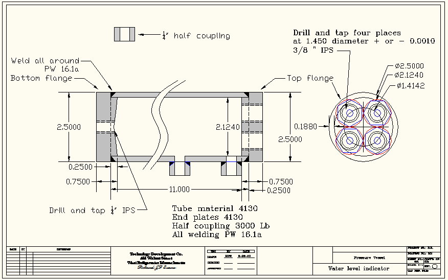
Boiler/Burner |
|||
|
|
|
|||||||||||||||||||||||||||
|
CAD Drawings in JPEG |
Click Photos to Enlarge |
||||||||||||||||||||||||||
|
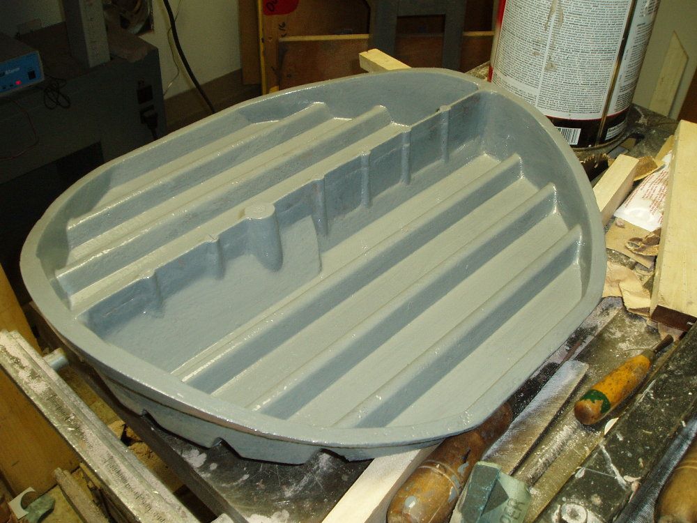
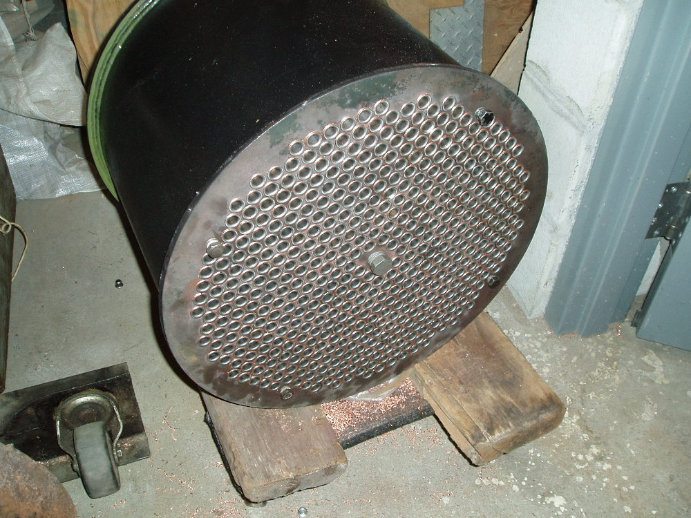
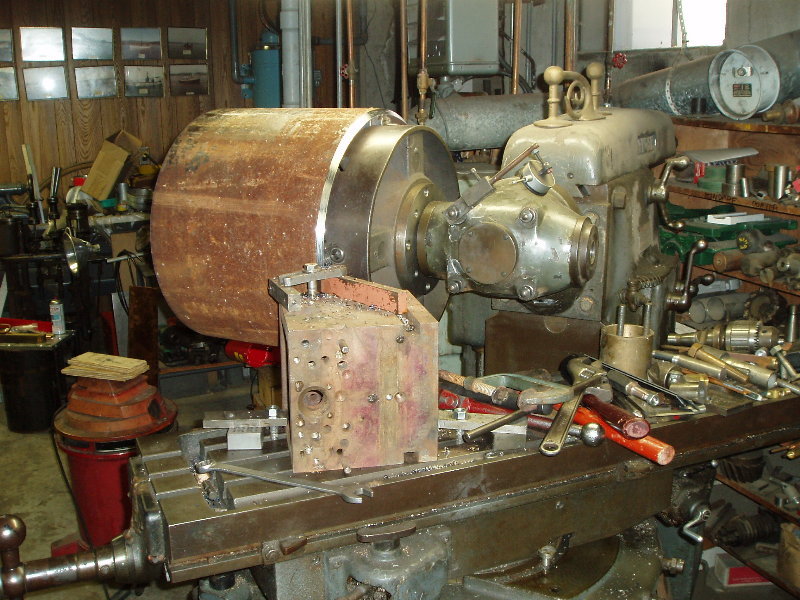
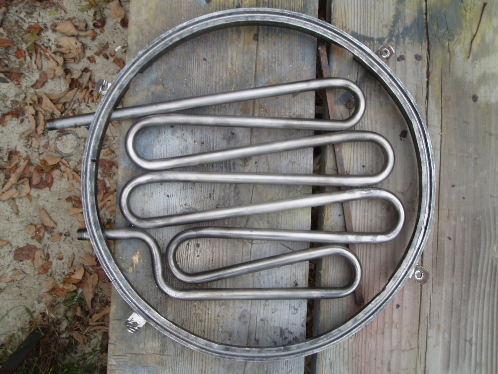
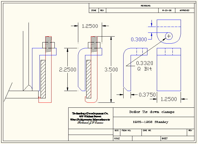
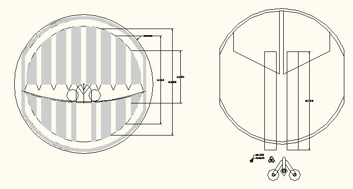
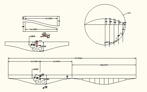
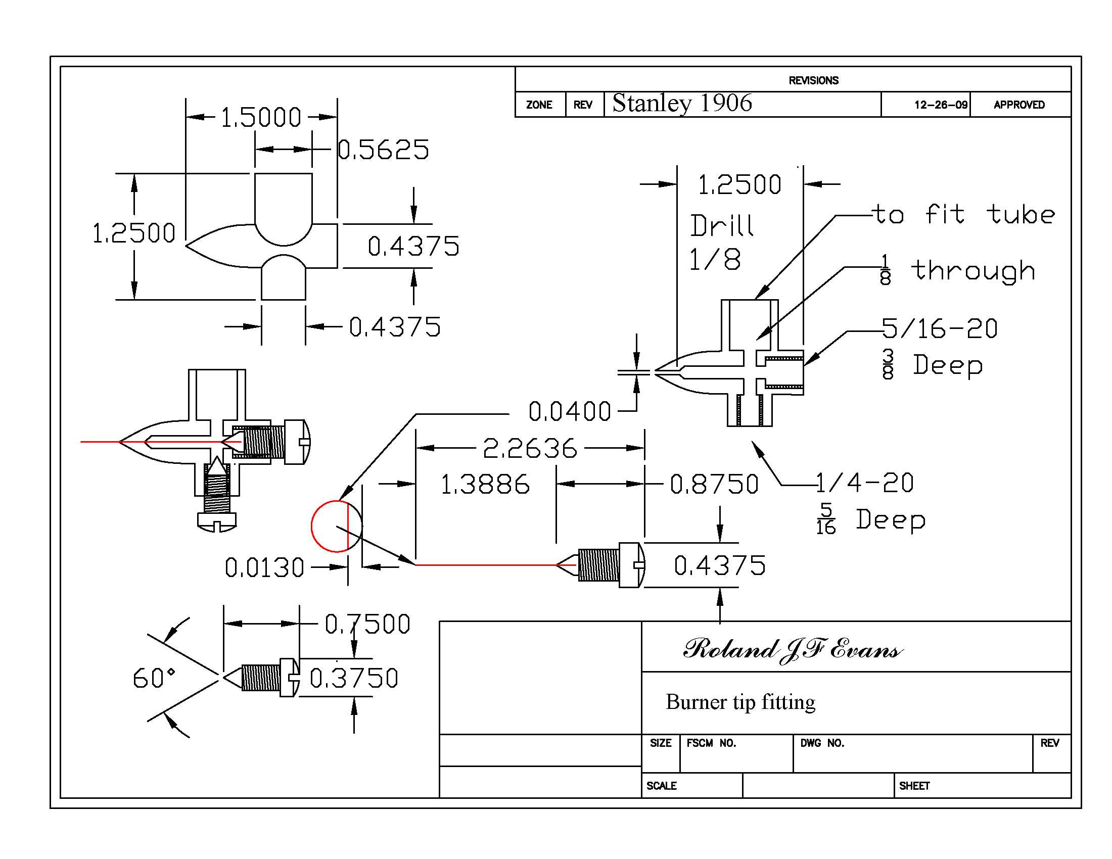
photoalbum\rolly\boiler-burner\10 HP Throttle.jpg photoalbum\rolly\boiler-burner\18 inch boiler Drill sheet-t.jpg photoalbum\rolly\boiler-burner\Boiler support.jpg photoalbum\rolly\boiler-burner\Boiler tie down clamp.jpg photoalbum\rolly\boiler-burner\Burner-1.jpg photoalbum\rolly\boiler-burner\Burner pan layout.jpg photoalbum\rolly\boiler-burner\Burner tip.jpg photoalbum\rolly\boiler-burner\Drill pattern.jpg photoalbum\rolly\boiler-burner\super heater & burner pan.jpg photoalbum\rolly\boiler-burner\super heater.jpg photoalbum\rolly\boiler-burner\Valve.jpg photoalbum\rolly\boiler-burner\Water level gauge-2.jpg photoalbum\rolly\boiler-burner\Water level Pressure vessel.jpg |
|
||||||||||||||||||||||||||
|
|||||||||||||||||||||||||||
|
|
|||
|
|
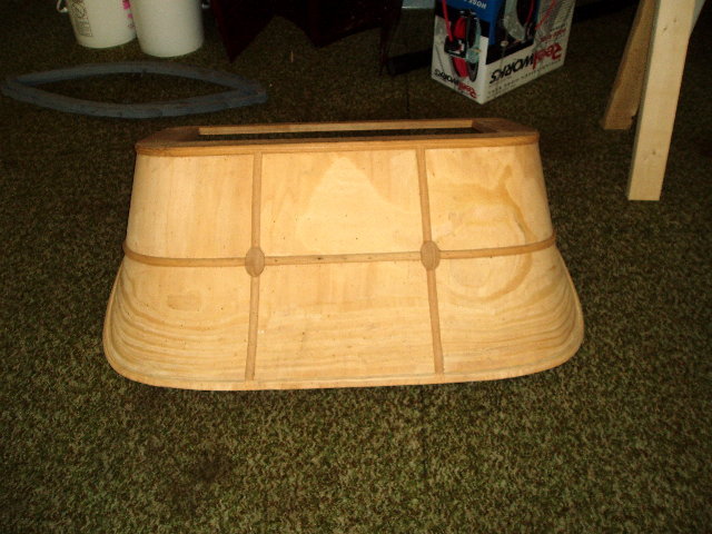
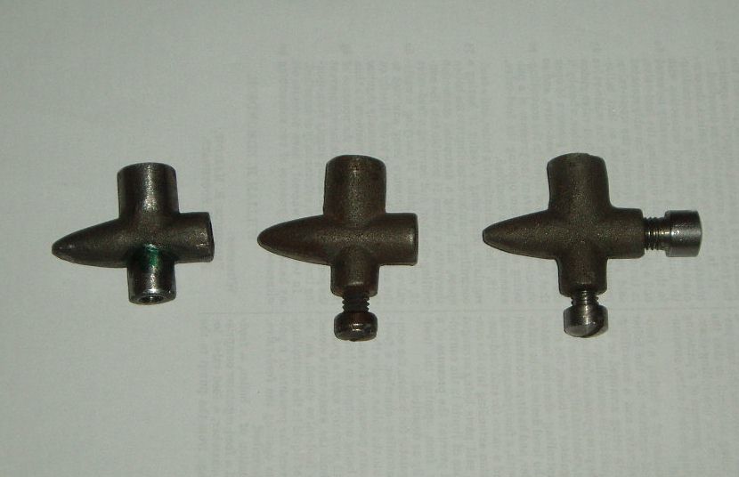
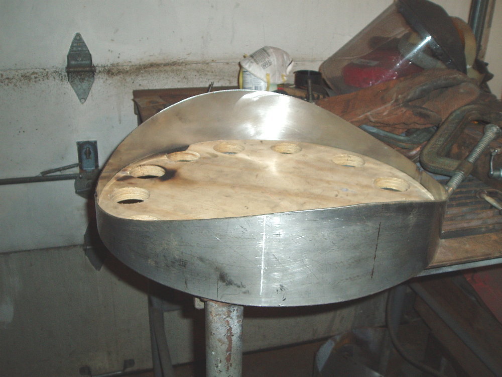
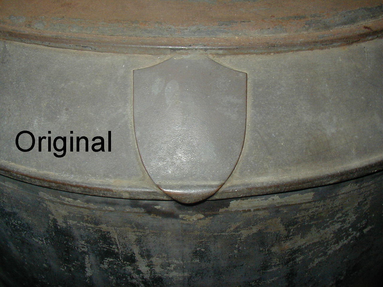
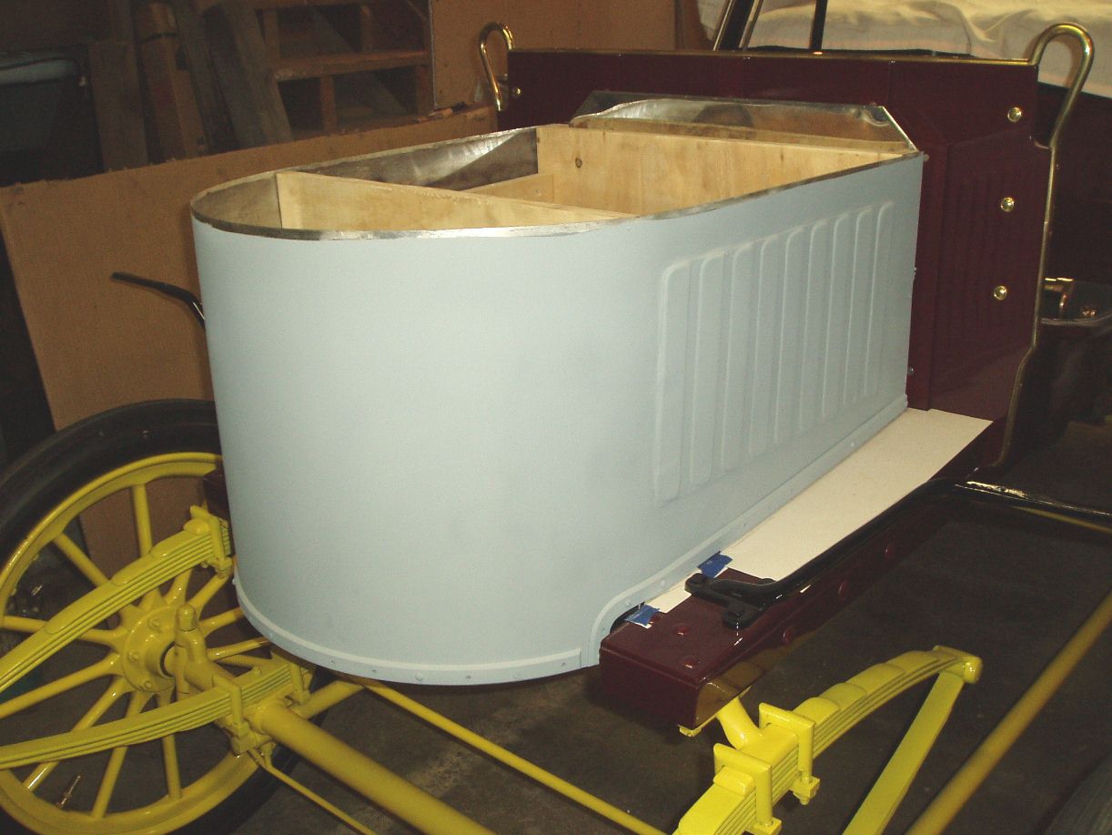
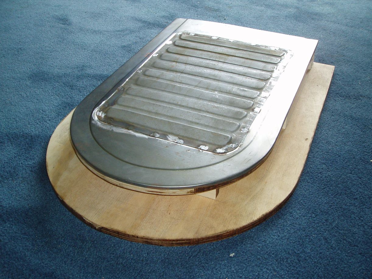
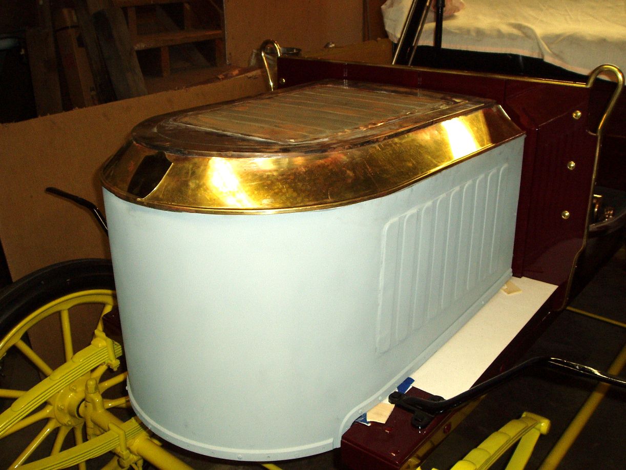
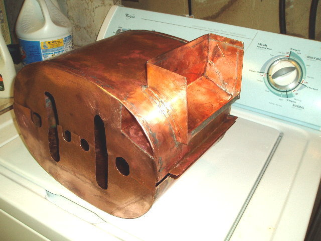
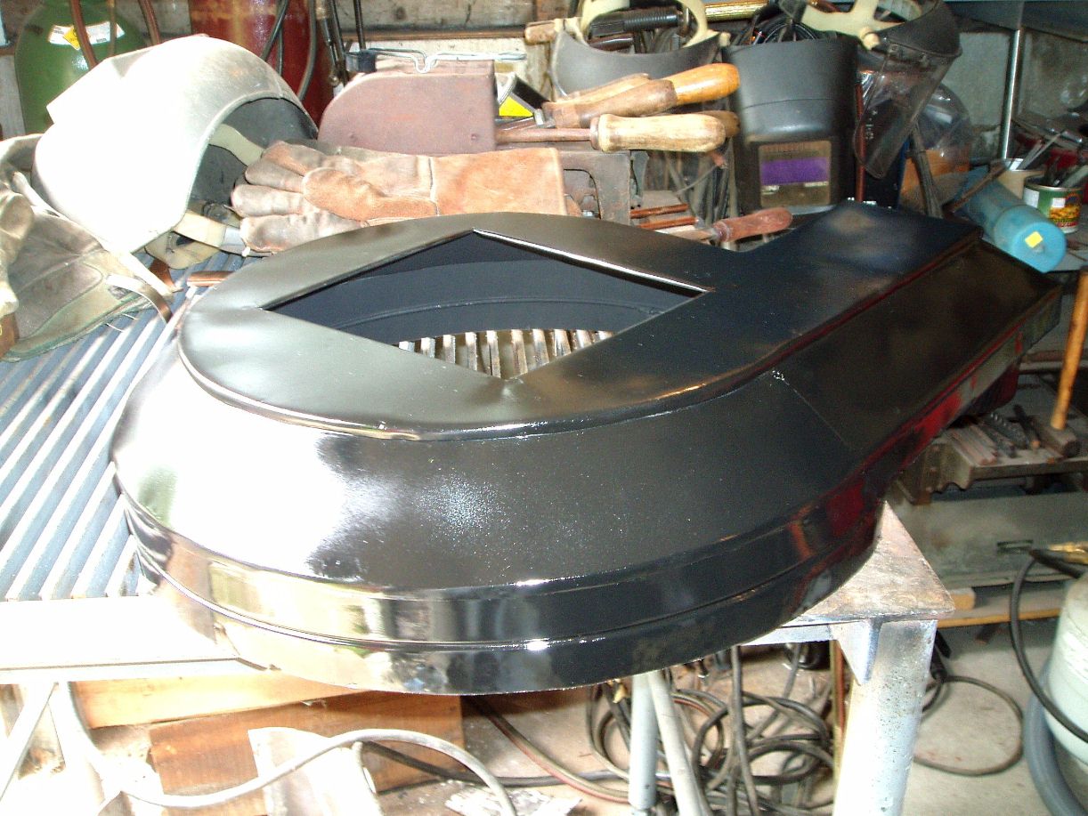
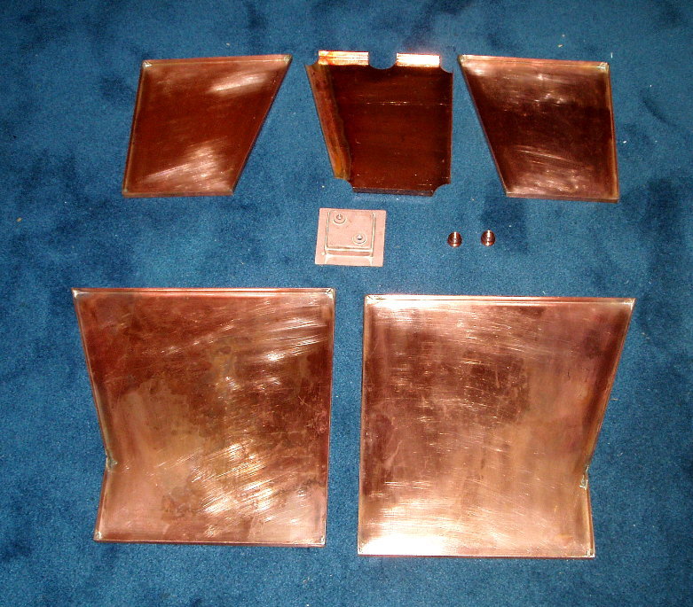
I was really trying to have some one make this for me but after many frustrating attempts 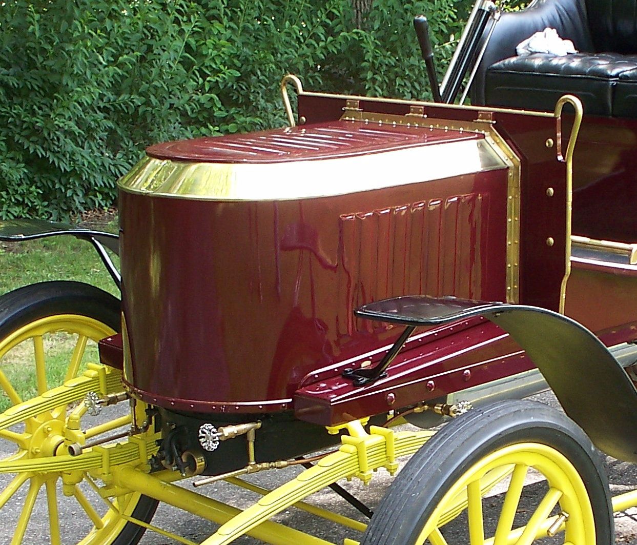 I
finely bit the bullet and took a stab at it. I had spent many hours
checking all the EX cars I came across and not one hood had the same
dimensions. All varied as much as a half-inch, to an inch. I did my own
drawings to fit my car and used all the old photos to acquire original
details. I
finely bit the bullet and took a stab at it. I had spent many hours
checking all the EX cars I came across and not one hood had the same
dimensions. All varied as much as a half-inch, to an inch. I did my own
drawings to fit my car and used all the old photos to acquire original
details.
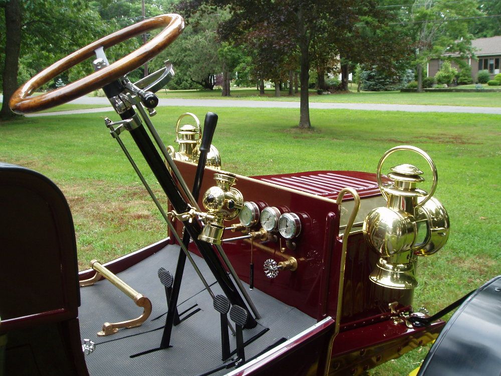
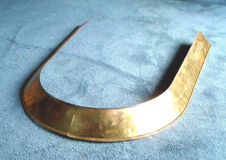
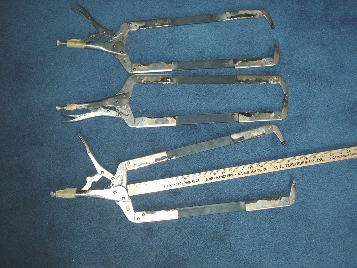
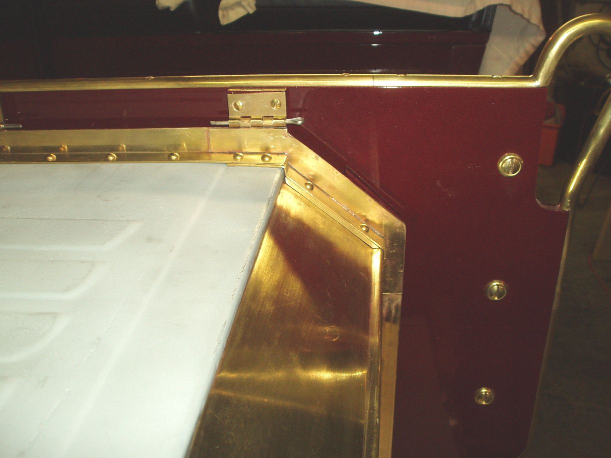
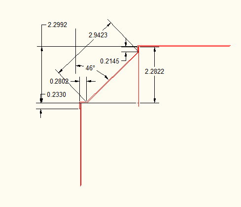
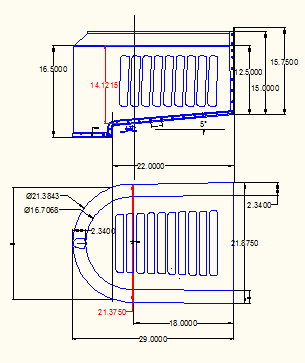
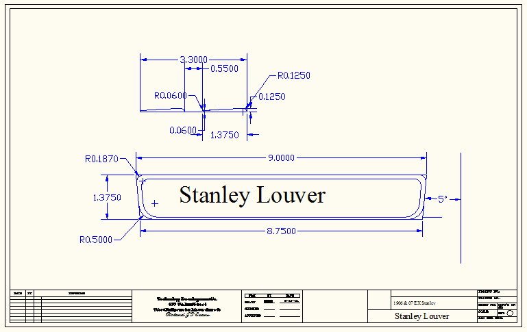
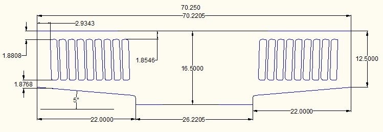
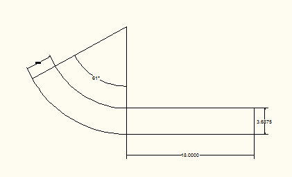
I ran into Daryl Kendall at the Eastern Steam car tour and he agreed to punch me out the louvered panels that could be welded into the sheet metal. I saw him do this once several years earlier. I had to buy a bead roller to make the joint on the sloped section of the hood. If I could make the brass sections well enough I knew I could make the rest. I had made and laid out cones before and the front of the hood was only half a cone. I set up and cut and rolled the brass, it looked good, I knew I was half way there. I bought a sheet of cold rolled sheet steel and went to town on the rest of the panels. About that time the UPS truck delivered Daryl panels. I set up and machined the trim for around the lower edge and ordered the brass angle stock for the trim around the back. |
||||||||||||
|
|
||||||||||||
|
CAD Drawings in JPEG |
Click Photos to Enlarge |
|||||||||||
|
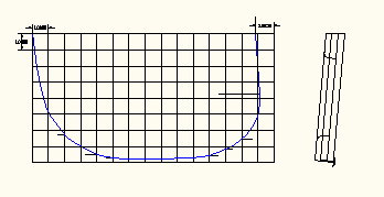
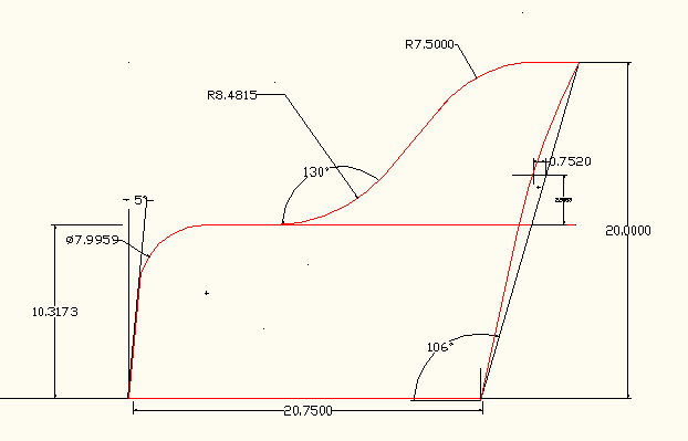
photoalbum\rolly\hood\Angle dimensions.jpg photoalbum\rolly\hood\Hood profile.jpg photoalbum\rolly\hood\Stanley Louvers.jpg |
|
|||||||||||
|
||||||||||||
|
||||||
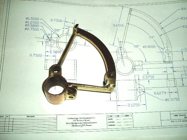
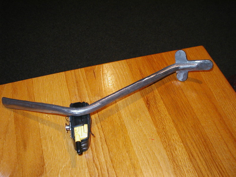
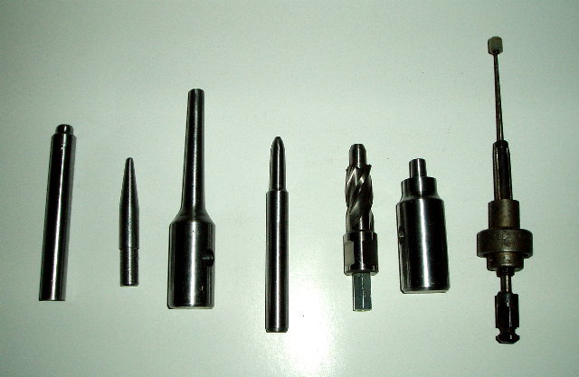
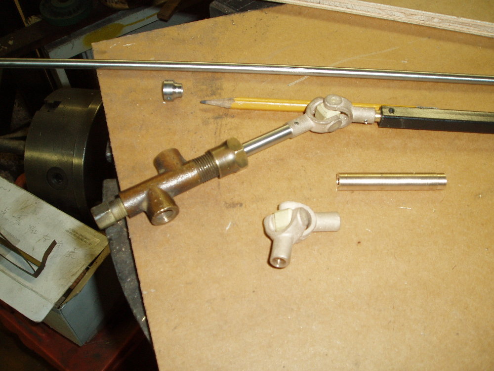
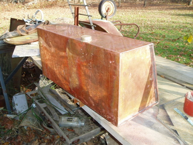
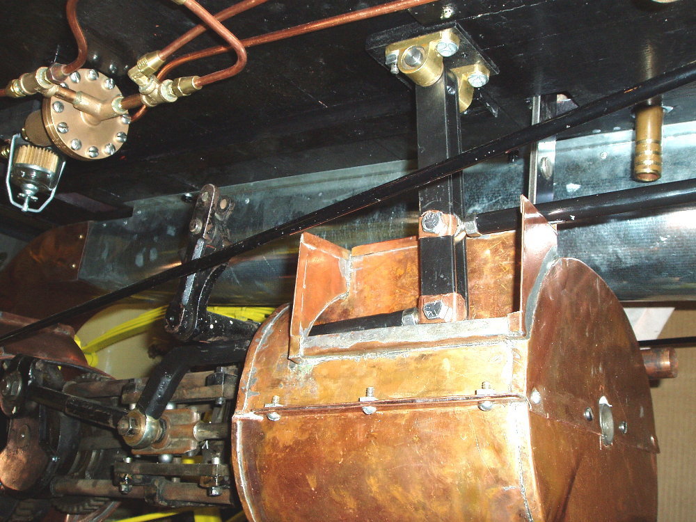
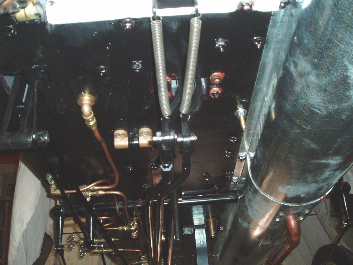
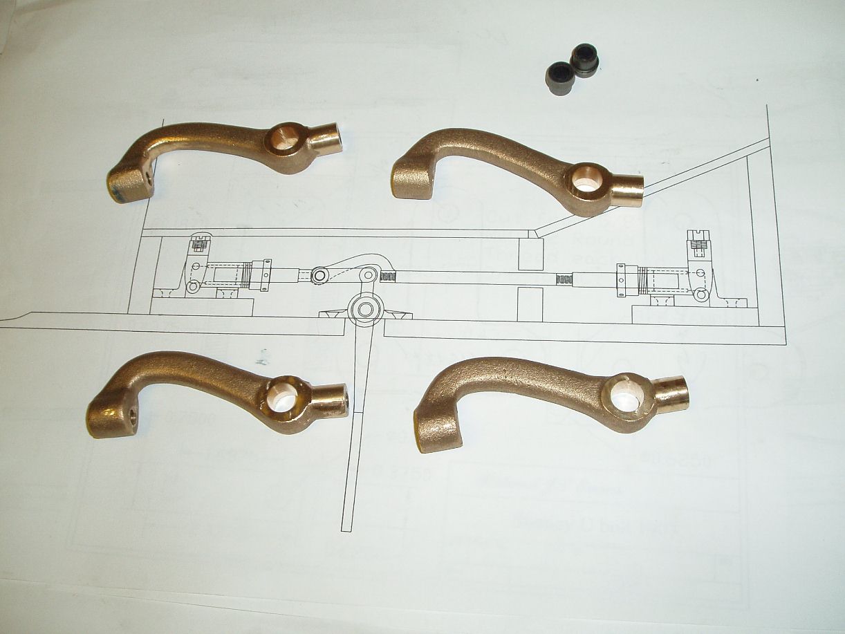
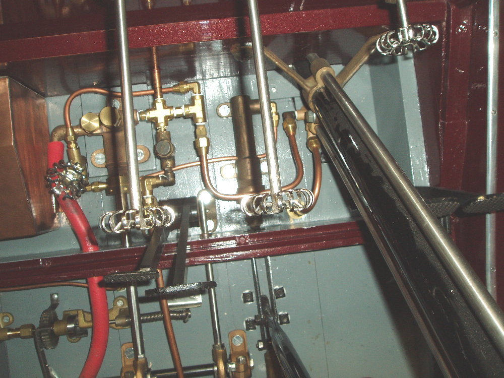
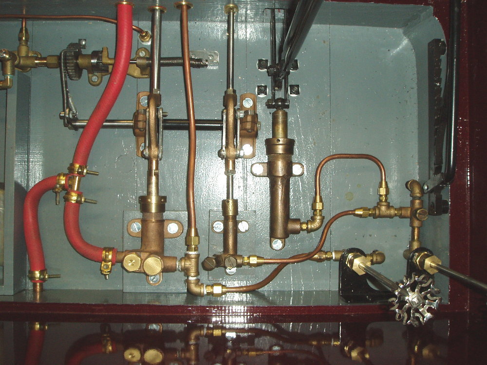
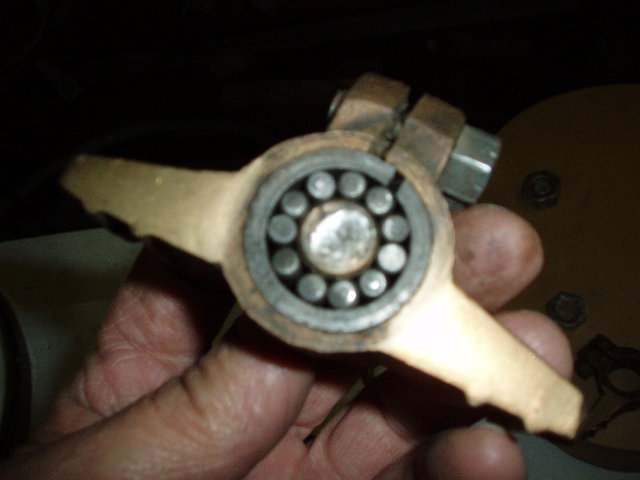
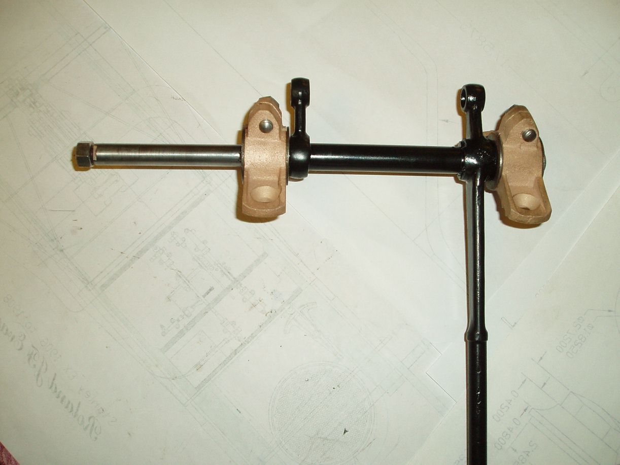
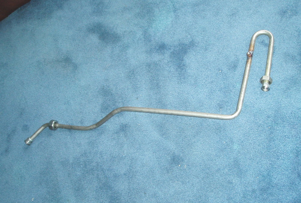
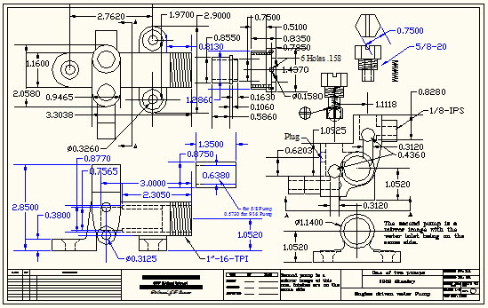
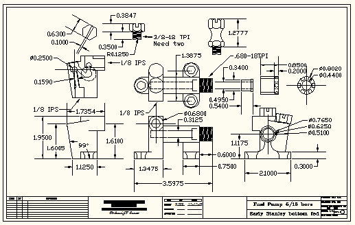
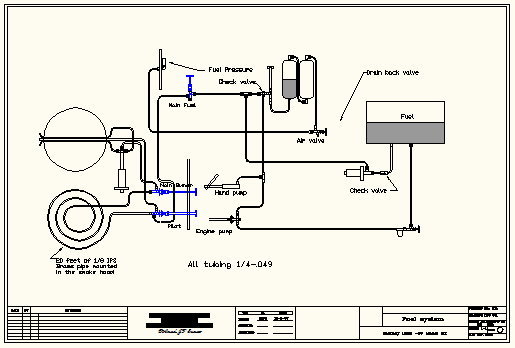
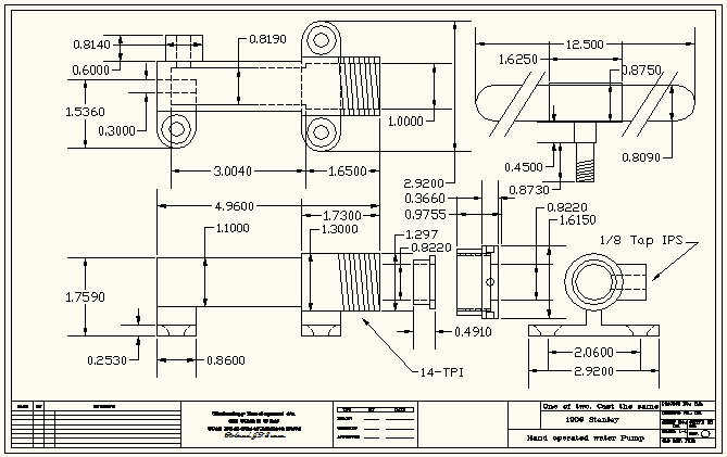
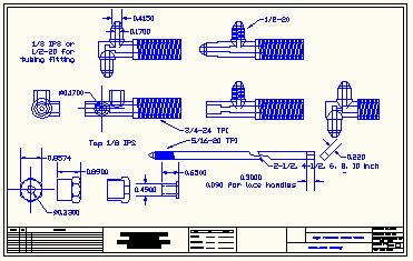
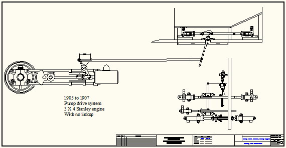
I am making this the last topic, I think there
is enough posted to give anyone a very good
over-view of what it takes to build a car, or start this
type of project.
|
|||||||||||||||||||||||||||||||||
|
|
|||||||||||||||||||||||||||||||||
|
CAD Drawings in JPEG |
Click Photos to Enlarge |
||||||||||||||||||||||||||||||||
|
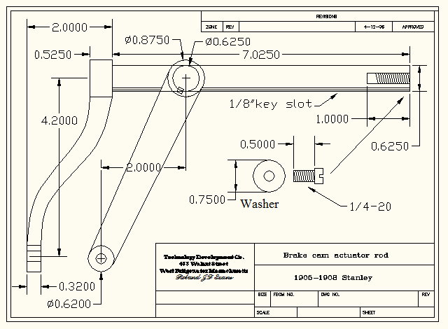
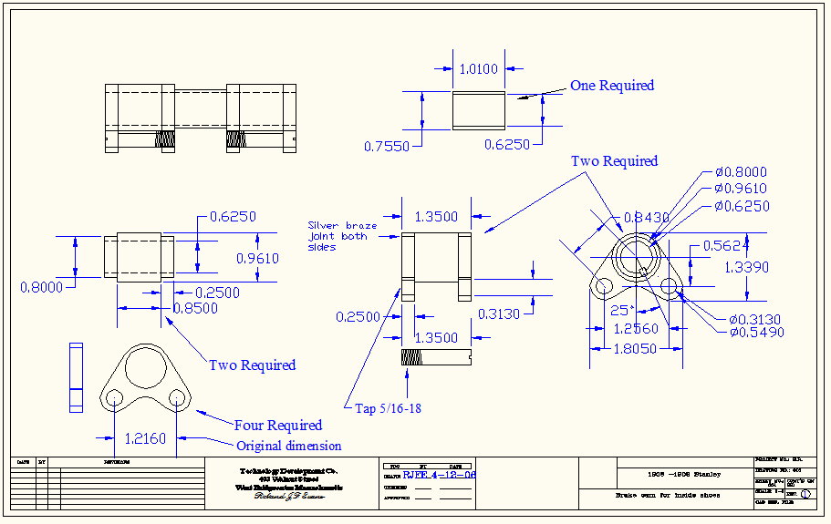
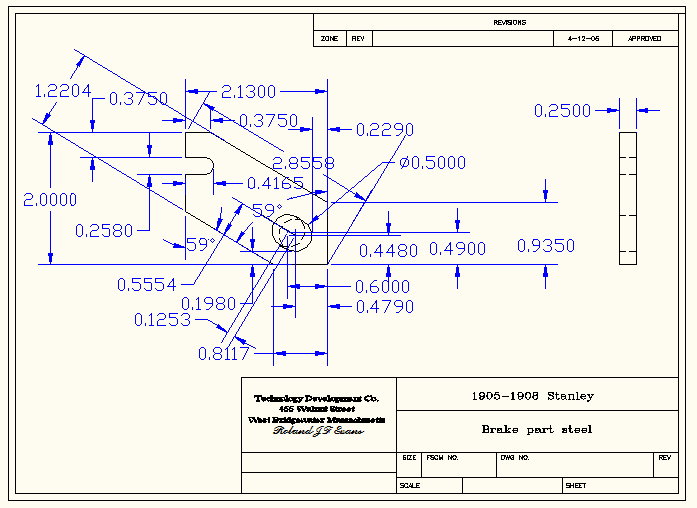
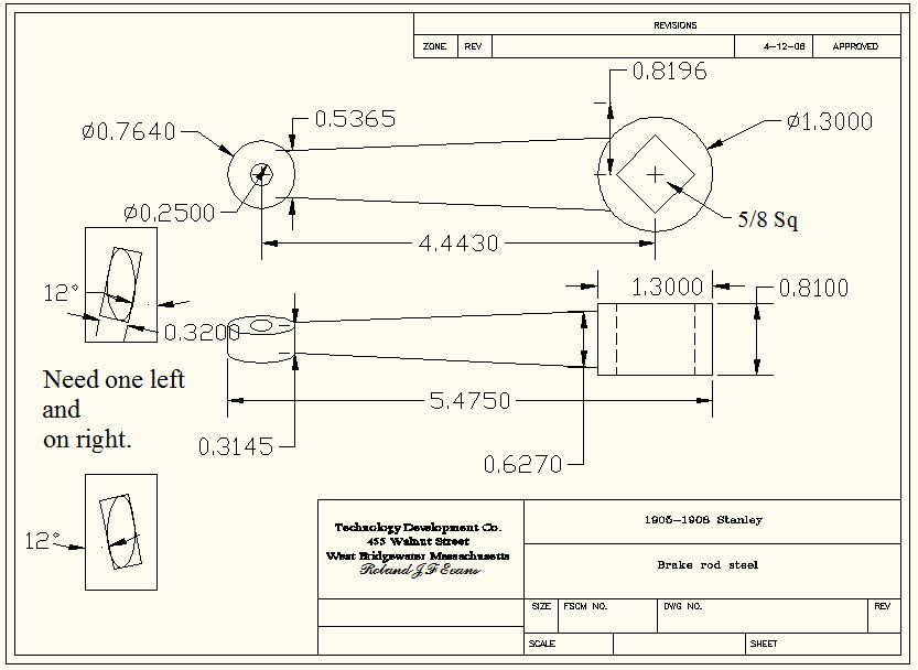
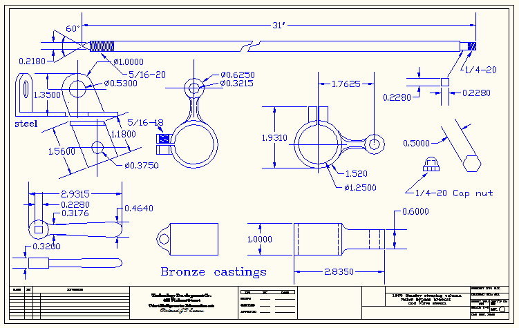
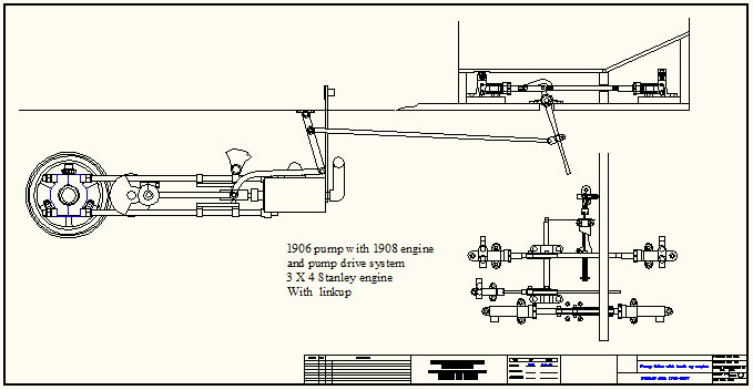
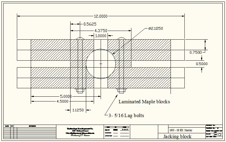
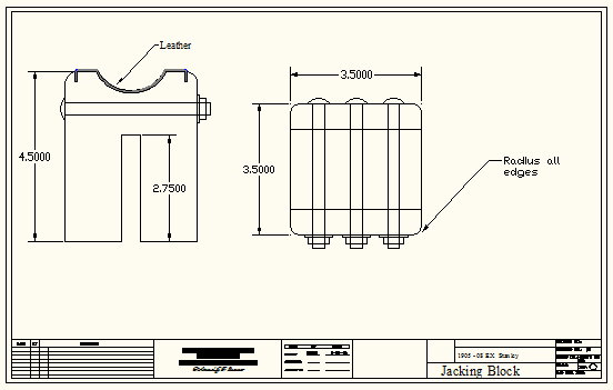
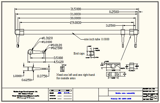
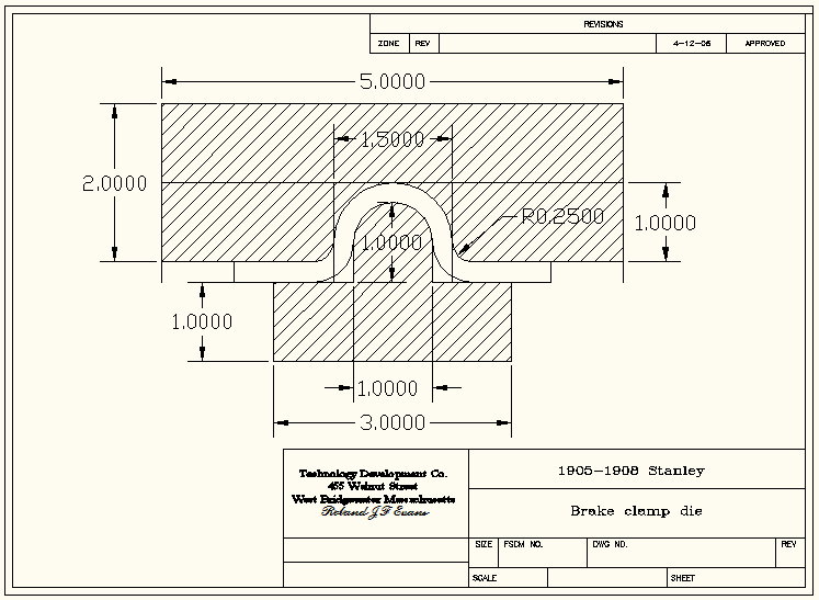
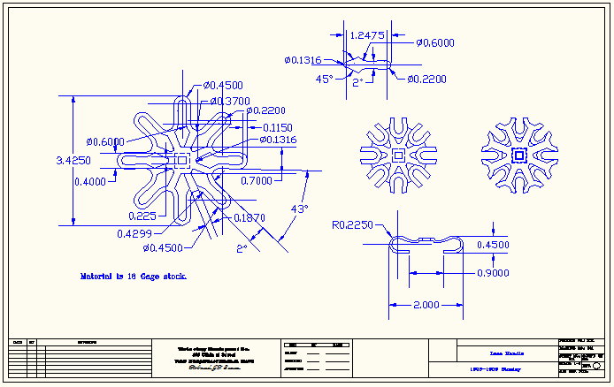
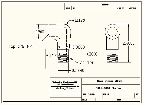
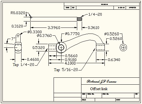
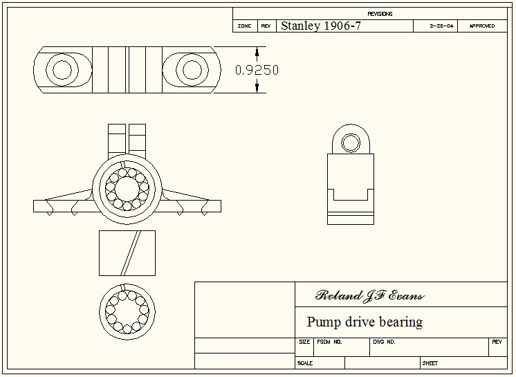
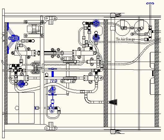
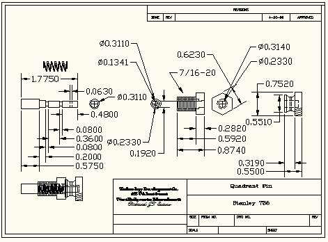
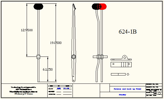
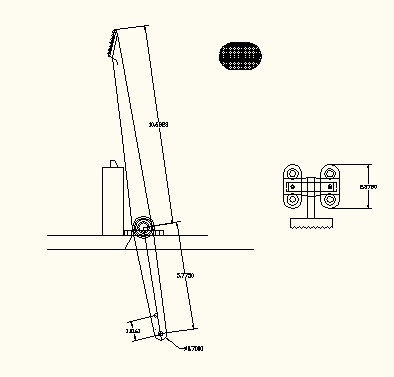
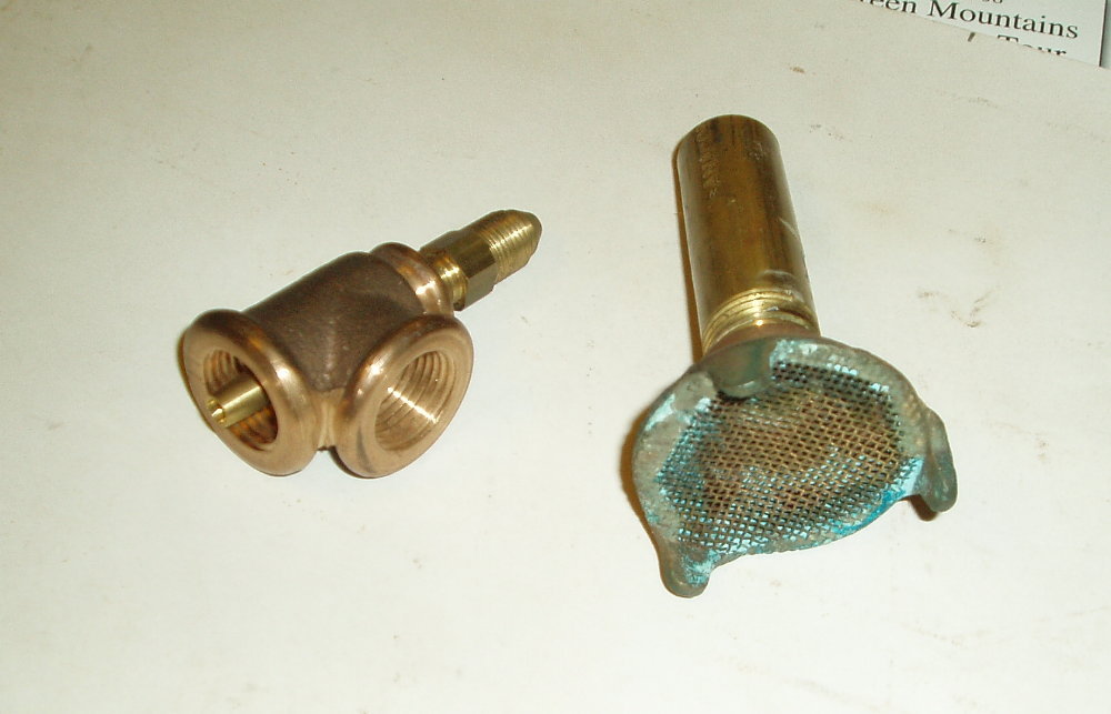
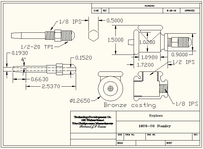
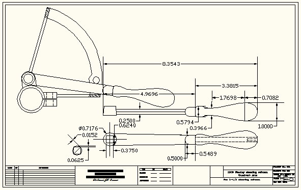
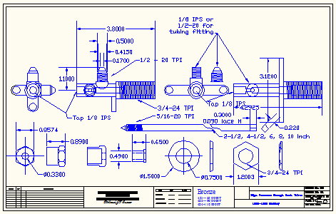
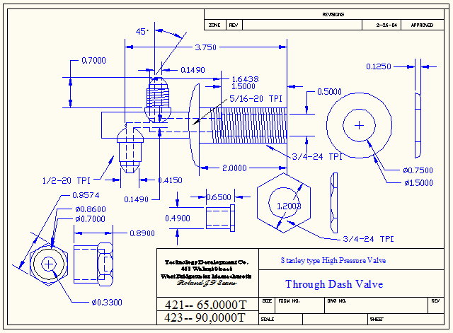
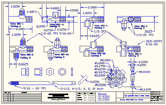
photoalbum\rolly\pumps,tanks,parts\1906 -07 pumps with 1908 drive.jpg photoalbum\rolly\pumps,tanks,parts\axle jacking block-1.jpg photoalbum\rolly\pumps,tanks,parts\axle jacking block-2.jpg photoalbum\rolly\pumps,tanks,parts\Brak arm-a.jpg photoalbum\rolly\pumps,tanks,parts\die for clamp-a.jpg photoalbum\rolly\pumps,tanks,parts\engine blow down valve.jpg photoalbum\rolly\pumps,tanks,parts\Engine driven water Pump 1909 Machineing Dr.jpg photoalbum\rolly\pumps,tanks,parts\engine hanger strap.jpg photoalbum\rolly\pumps,tanks,parts\Exhaust Duct.jpg photoalbum\rolly\pumps,tanks,parts\Fuel Pump bottom fed.jpg photoalbum\rolly\pumps,tanks,parts\Fuel System EX.jpg photoalbum\rolly\pumps,tanks,parts\Hand operated Pump .jpg photoalbum\rolly\pumps,tanks,parts\High Pressure Valves.jpg photoalbum\rolly\pumps,tanks,parts\Lace Handle.jpg photoalbum\rolly\pumps,tanks,parts\low water alarm.jpg photoalbum\rolly\pumps,tanks,parts\Main steam elebow-1.jpg photoalbum\rolly\pumps,tanks,parts\Off set link.jpg photoalbum\rolly\pumps,tanks,parts\pump drive bearing.jpg photoalbum\rolly\pumps,tanks,parts\Pump drive with no Hookup.jpg photoalbum\rolly\pumps,tanks,parts\Pump Layout.jpg photoalbum\rolly\pumps,tanks,parts\Quadrant pin.jpg photoalbum\rolly\pumps,tanks,parts\Reverse Hook up Pedal.jpg photoalbum\rolly\pumps,tanks,parts\Reversing pedal.jpg photoalbum\rolly\pumps,tanks,parts\Siphon and pickup head .JPG photoalbum\rolly\pumps,tanks,parts\Siphon.jpg photoalbum\rolly\pumps,tanks,parts\Throttle quadrant .jpg photoalbum\rolly\pumps,tanks,parts\Throttle quadrant Handle .jpg photoalbum\rolly\pumps,tanks,parts\Through Dash Valves.jpg photoalbum\rolly\pumps,tanks,parts\Through Dash Valves-M dwg.jpg |
|
||||||||||||||||||||||||||||||||
|
|||||||||||||||||||||||||||||||||
